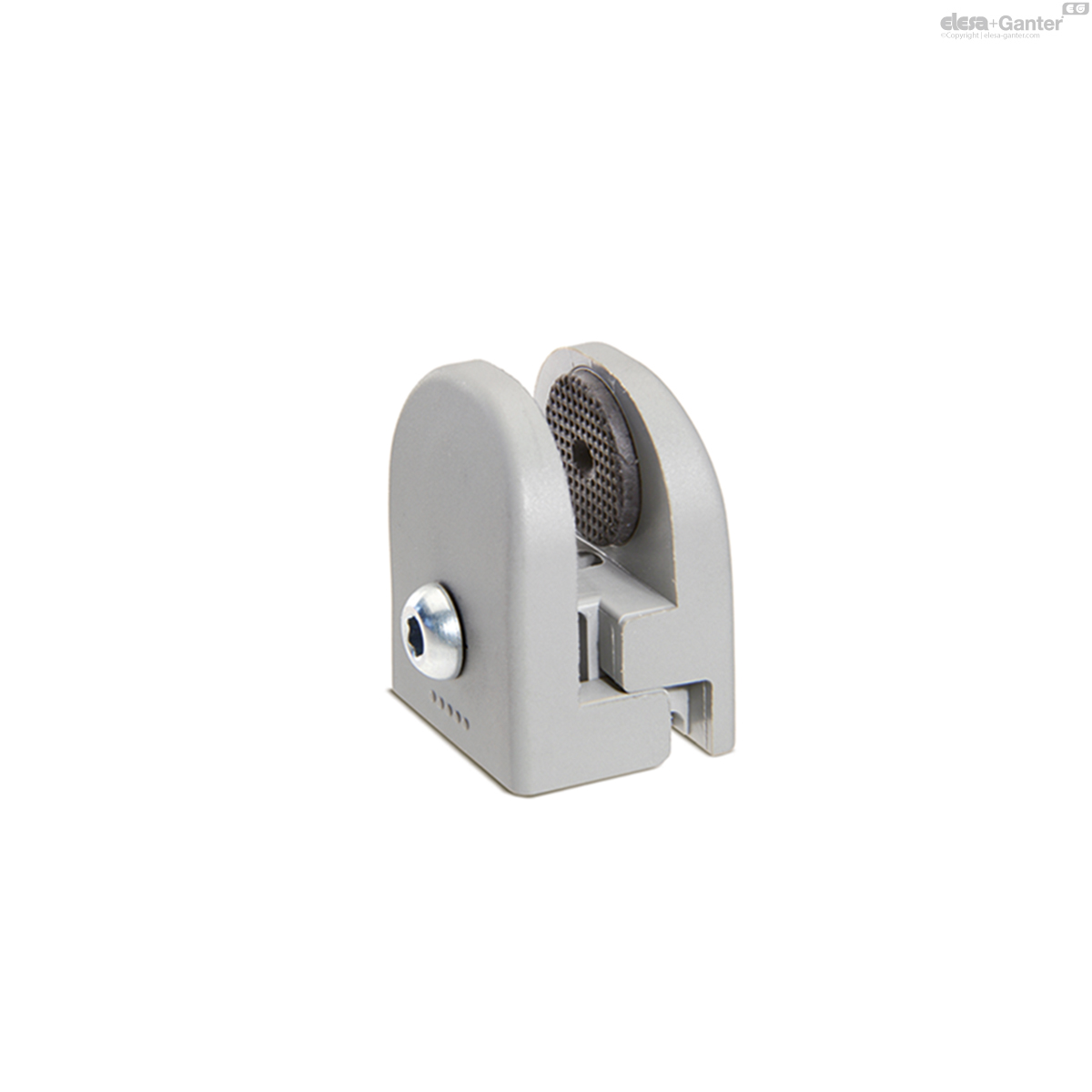
PC
Panel support clamps
Technopolymer
PC
Panel support clamps
Steel screw and nut

PC-SST
Panel support clamps
Stainless steel screw and nut
Description
Main specifications
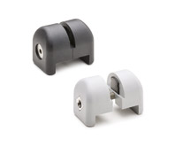
Material
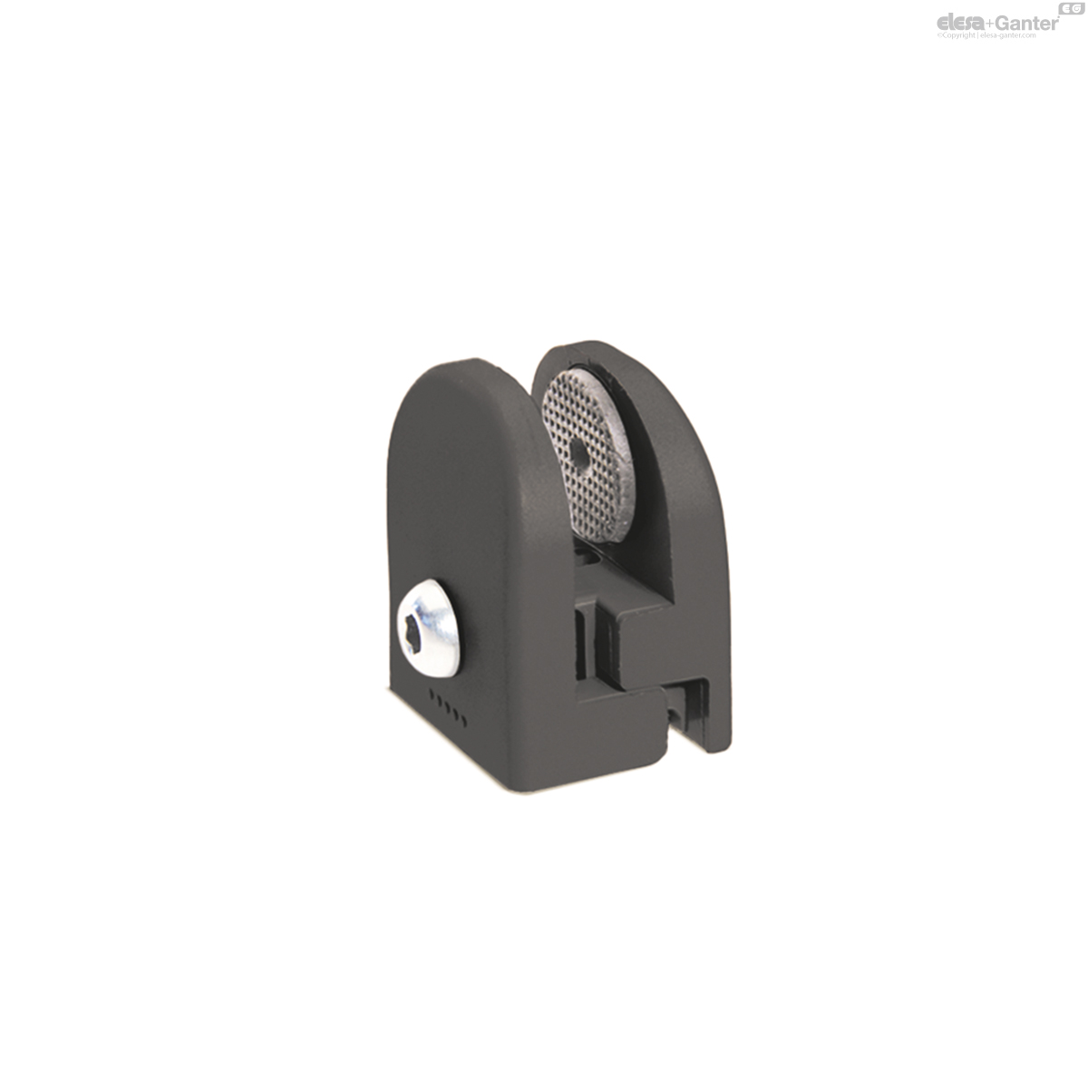
Glass-fibre reinforced polyamide based (PA) technopolymer, RAL 9005 (C9) black colour or grey RAL 7042 colour, matte finish.
Pads
Thermoplastic elastomer, hardness 80, Shore A, overmoulded.
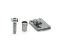
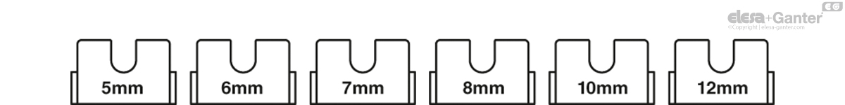
Adjusting spacers (included in the supply)
Polyamide based (PA) technopolymer, RAL 7042 grey colour, for fastening the clamp to panels of variable thickness (see table).
Standard executions
- PC: steel screw and nut.
- PC-SST: stainless steel screw and nut.

| s panel thickness [mm] | Adjusting spacer to be used PC.35-4-8 |
| 3.1 < s < 4.1 | - |
| 4.1 < s < 5.1 | 5 mm |
| 5.1 < s < 6.1 | 6 mm |
| 6.1 < s < 7.1 | 7 mm |
| 7.1 < s < 8.1 | 8 mm |
| s panel thickness [mm] | Adjusting spacer to be used PC.35-6-12 |
| 6.1 < s < 7.1 | - |
| 7.1 < s < 8.1 | 8 mm |
| 9.1 < s <10.1 | 10 mm |
| 11.1 < s <12.1 | 12 mm |
General information
Features and applications
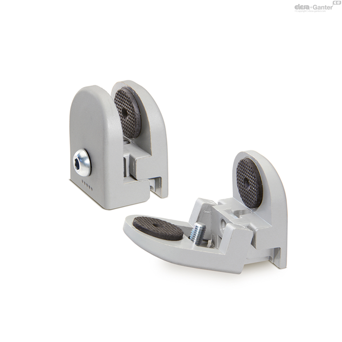
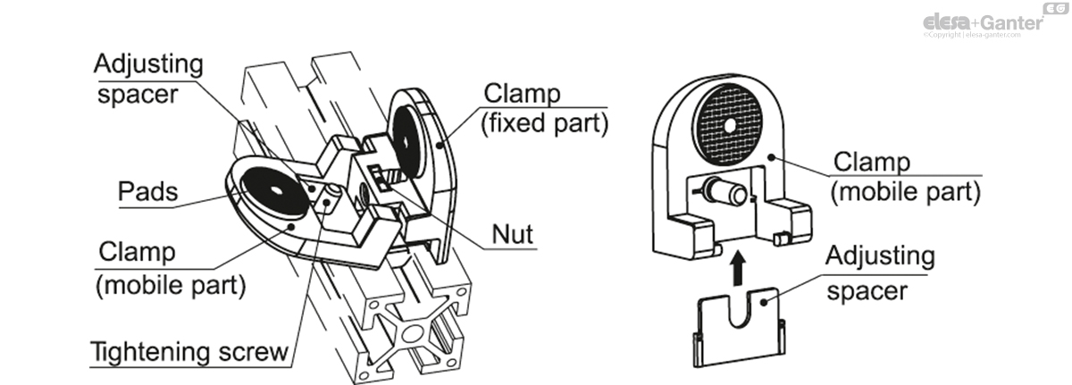
- The product is in compliance with the Machine Directive (2006/42/CE) that provides for the retention of all the clamping elements even in the open position (ELESA patent). The two parts of the clamp are connected by means of an articulated joint and they have got a seat for housing a steel or stainless steel screw and M5 nut.
- The special dimensions of the clamp allow its assembly on profiles with a width of 25 mm or higher.
- The panel assembly into the clamp does not require any drilling which may cause cracks in the panel.
- The pads deform upon tightening to guarantee the perfect fastening of the inserted panel.
- The chemical bond of the overmoulded pads makes them a single body with the clamp. The embossed surface avoid any possible sticking of the pad to the panel over the time.
- The tightening clamp allows a direct assembly of panels with thickness from 3.1 mm to 4 mm. The assembly of panels with higher thicknesses, up to a maximum of 8 mm, is possible by inserting the spacers into a specific cavity provided in the clamp.
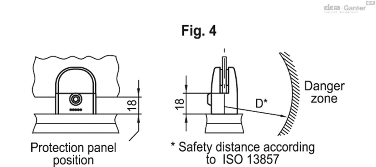
- To prevent machine danger zones being reached through any opening in the machine protection structure made of panels fixed with the PC clamp, it is necessary to keep a safety distance (Fig. 4) according to ISO 13857, section 4.2.4 (the safety distance is the minimum distance required between a protection structure and a potentially dangerous component of the machine).
Technical data
If the clamp is opened, the tightening screw does not yield below an extraction force of 250 N, without coming out from its housing.
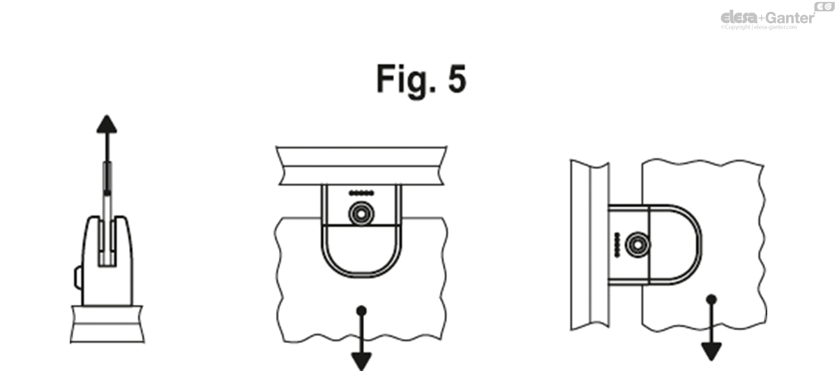
During the tests carried out in our laboratories under controlled temperature and humidity (23°C-50% R.H.), under given conditions of use and for a limited period of time, the maximum load of each clamp is of 100 N (fig. 5).
The tightening screw of the panel and the assembly screws of the clamp on the profile have got the same hexagonal seat. Thus, it is possible to make the assembly by using only one hexagonal key (Key 4).
Maximum tightening torque for the screw = 3.5 Nm.


Instructions of use
Assembly of the clamp on the profile
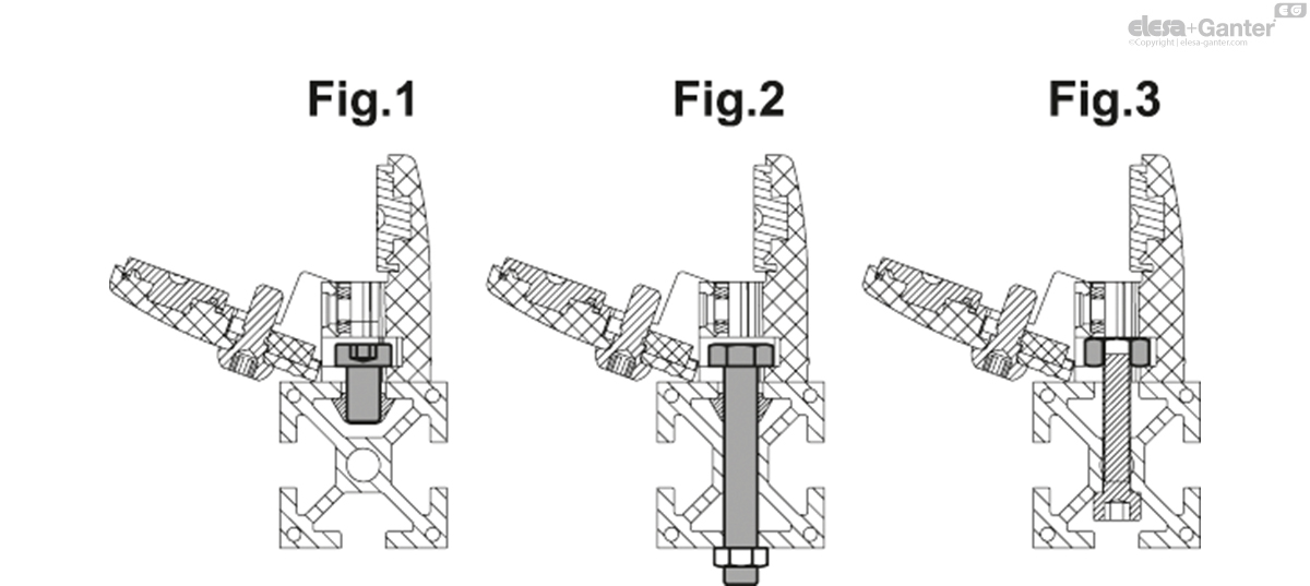
- M6 shorted cylindrical head screw with DIN 7984 hexagon socket (fig.1).
- DIN 933 M6 hexagonal head screw (fig. 2).
- DIN 439B or DIN 934 M6 hexagonal nut (fig. 3).

PC
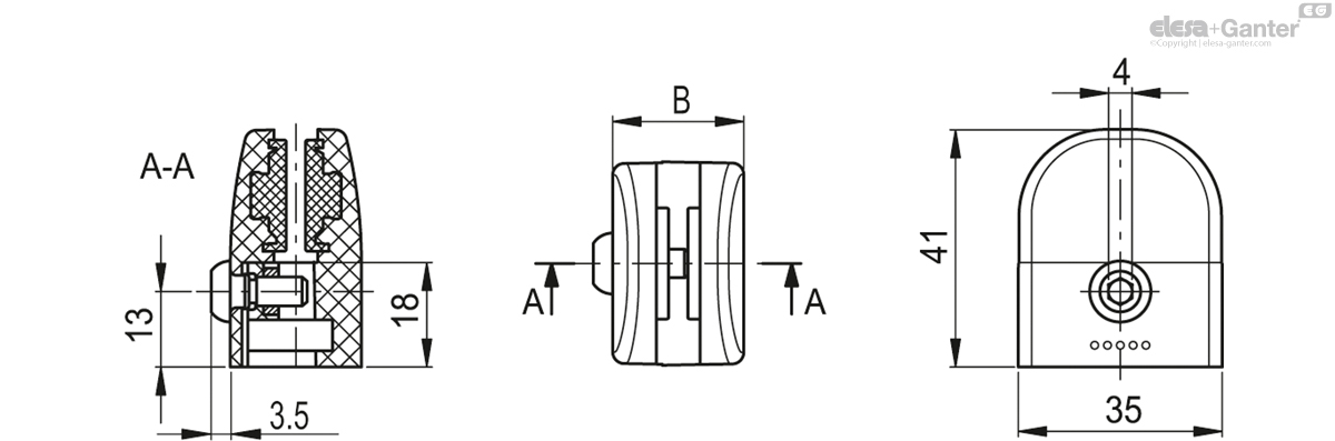
| Color | B | ||||
|---|---|---|---|---|---|
| Code | Description | Actions | |||
| 49301 | PC.35-4-8 | C34 - RAL 7042 | 22.5 | 39 |
|
| 49301-C9 | PC.35-4-8-C9 | C9 - RAL 9005 | 22.5 | 39 |
|
| 49302 | PC.35-6-12 | C34 - RAL 7042 | 26 | 44 |
|
| 49302-C9 | PC.35-6-12-C9 | C9 - RAL 9005 | 26 | 44 |
|

Enquiry Now
To allow us to respond to your enquiry promptly, please provide all required information.