LAC-FL
Cam levers
for quick clamping, technopolymer
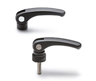
LAC-FL-F-SST
Cam levers
Without anti-rotation reference pin
LAC-FL-O-SST
Cam levers
With anti-rotation reference pin


Description
Main specifications
Cam lever body
Glass-fibre reinforced polyamide based (PA) technopolymer, black colour, matte finish.
Elastic connecting pin
AISI 301 stainless steel.
Cam sliding base
Polyamide based (PA) technopolymer, black colour.
Threaded pin
Polyamide-based SUPER-technopolymer (PA), black colour.
Elastic expansion retention element
Synthetic rubber, hardness 60, Shore A.
Self-locking nut and washer
AISI 304 stainless steel.
Standard executions
- LAC-FL-F-SST: the lever is free to position itself in any direction.
- LAC-FL-O-SST: the lever is always kept oriented in the desired position thanks to the anti-rotation reference pin.
General information
Features and applications
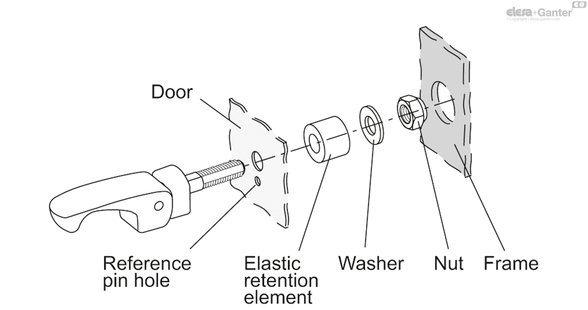
The cam lever is a device that allows quick and effective clamping of a panel (for example a door) to a structure (for example a frame), guaranteeing perfect closure even in the event of vibrations or any misalignment between the two elements.
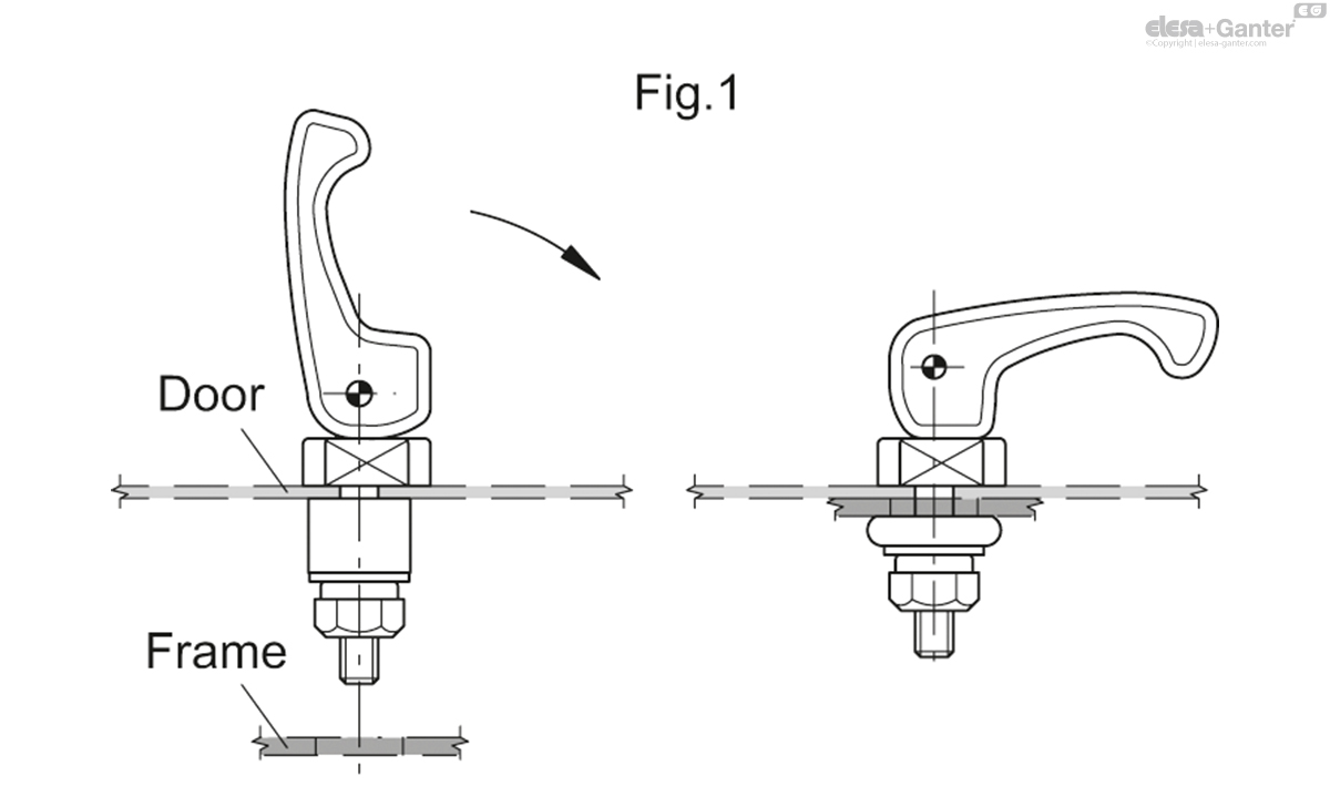
By turning the lever clockwise, the expansion of the elastic retaining element is obtained and therefore the two elements are locked together (fig. 1).
The product is also suitable for applications on equipment subject to frequent cleaning with jets of water or steam or in any case in environments where special attention is required from a hygienic point of view.

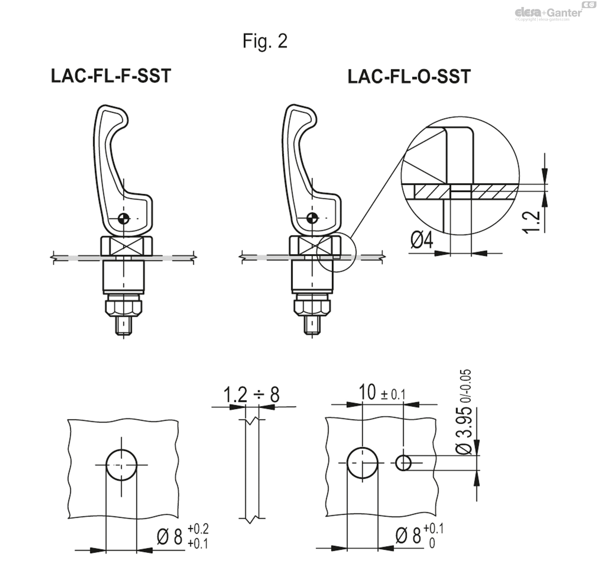
Assembly instructions
Assembly instructions
Drill a hole in the panel (e.g. door) on which the lever is to be fixed according to the templates indicated (fig. 2).
The presence of the reference hole diameter 3.95 mm of the peg (LAC-FL-O-SST execution) makes it possible to keep the lever oriented in the desired position.
During mounting, the pin must enter the hole with slight interference.
Drill a hole in the panel to be clamped (frame, for example) according to the size template shown in the table (fig. 3).
Assemble the lever and the cam sliding base to the panel (hatch), position the elastic retaining element and the washer on the opposite side, lock with the self-locking nut until any movement is completely eliminated by slightly compressing the elastic retention element.

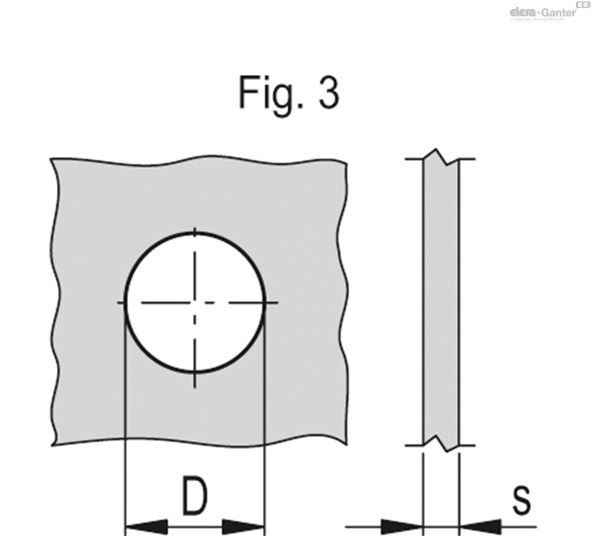
| s | D | Fmax* [N] |
| 1.2 ÷ 3.2 | 19 | 330 |
| 3.2 ÷ 4.8 | 19.5 | 660 |
| 4.8 ÷ 6.4 | 20 | 550 |
| > 6.4 | 20.5 | 220 |
* Maximum holding force exerted in the short term by the elastic retention element.
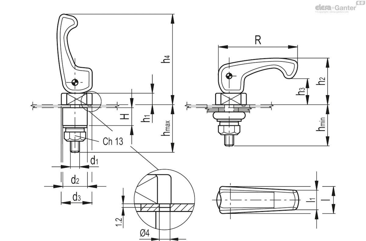
LAC-FL-O-SST
| R | d | H | hmin | hmax | h1 | h2 | h3 | h4 | d1 | d2 | d3 | l | l1 | ||||
|---|---|---|---|---|---|---|---|---|---|---|---|---|---|---|---|---|---|
| Code | Description | Actions | |||||||||||||||
| 34103 | LAC-FL.55-O-SST | LAC-FL.55-O-SST | 55.5 | 12.5 | 28 | 32 | 8 | 32.5 | 18.5 | 63.5 | M8x22 | 17.5 | 21.5 | 18.5 | 13 | 30 |
|

Enquiry Now
To allow us to respond to your enquiry promptly, please provide all required information.
Related Products