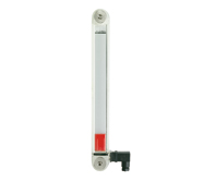
HCY-E-ST
Oil electrical level indicators
with MIN level and MAX temperature electrical sensors, technopolymer

Description
Main specifications
Material
Transparent polyamide based (PA-T) technopolymer. Highly resistant to shocks, solvents, oils with additives, aliphatic and aromatic hydrocarbons, petrol, naphtha, phosphoric esters.
Avoid contact with alcohol or detergents containing alcohol.
Screws
Nickel-plated brass with hexagon socket.
Packing rings
NBR synthetic rubber O-Ring.
Float
Polyamide based (PA) technopolymer in red colour, with a built-in magnetic element to activate the electric contact when the oil level drops to the minimum set at 40mm over the screw axis (dimension l).
MIN level electrical sensor
It generates an electric signal when the oil level reaches the minimum level.
The inside of the cavity where the sensor is contained is completely resinated in order to increase the thermal and electric insulation.
Connector
Right side output including protection against water sprays (protection class IP 65 according to EN 60529-).
MAX temperature electrical sensor (80°C)
It is set at a standard intervention temperature of 80°C, placed close to a metallic plate which serves as a conductor of the heat of the fluid for a faster transmission and a lower dissipation. The inside of the cavity where the sensor is contained is completely resinated in order to increase the thermal and electric insulation.
For a correct assembly see Warnings.
Contrast screen
White lacquered aluminium. The housing, in the appropriate external rear slot, guarantees the best protection from direct contact with fluid.
It can be taken out before assembly to allow the insertion of level lines or words.
Screw-covers
Polyamide based technopolymer, grey colour.
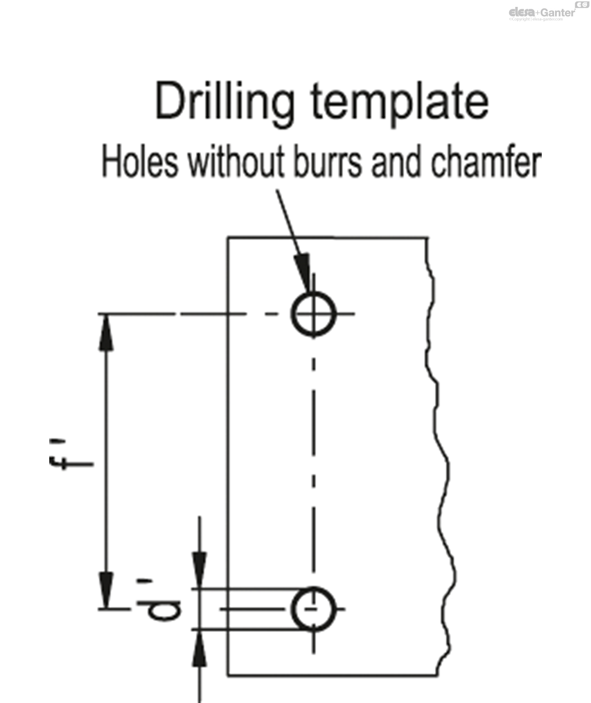
Standard executions
- HCY-E-ST-NO: with electrical contact normally open.
- HCY-E-ST-NC: with electrical contact normally closed.
Maximum continuous working temperature
80°C (with oil).
General information
Technical data
In laboratory tests carried out with mineral oil type CB68 (according to ISO 3498) at 23°C for a limited period of time, the weld stood up to: 14 bar (HCY.76), 9 bar (HCY.127) and 8 bar (HCY.254).
For use with other fluids and under different pressure and temperature conditions, please contact ELESA Technical Department.
In any case we suggest to verify the suitability of the product under the actual working conditions.
Electrical features
| Electrical features | MIN level sensor |
| Tension feed | AC/DC |
| Electric contacts | NO normally open NC normally closed |
| Maximum applicable voltage | NC: 150 Vac, 150 Vdc NO: 230 Vac, 230 Vdc |
| Maximum commutable opening capacity | NC: 1A NO: 2A |
| Maximum commutable power | NC: 20 W / 20 V.A. NO: 40 W / 40 V.A. |
| Cable gland | Pg 7 (for cables in sheath with Ø 6 or 7 mm) |
| Conductors cross-section | Max. 1.5 mm2 |
| Electrical features | MAX temperature sensor | |
|---|---|---|
| Tension feed | AC/DC | |
| Electric contacts | NO normally open NC normally closed | |
Voltage / Maximum applicable voltage | 250 Vac- 10 A | (resisteve loads) |
| 60 Vdc - 3 A | ||
| Cable gland | Pg 7 (for cables in sheath with Ø 6 or 7 mm) | |
| Conductors cross-section | Max. 1.5 mm2 | |
| Do not mount this indicator in proximity to magnetic fields. | ||
Other executions
Special executions on request
- Column level indicators in different materials (polycarbonate), for use with special fluids and/or at high temperatures.
- AISI 316 stainless steel or nickel-plated brass screws
- Column level indicators with change-over electrical contact.
- Execution with PT100 temperature electrical probe for connection to PLC.
- Electrical sensors set at the following temperatures: 50°, 60°, 70°C.
Instructions of use
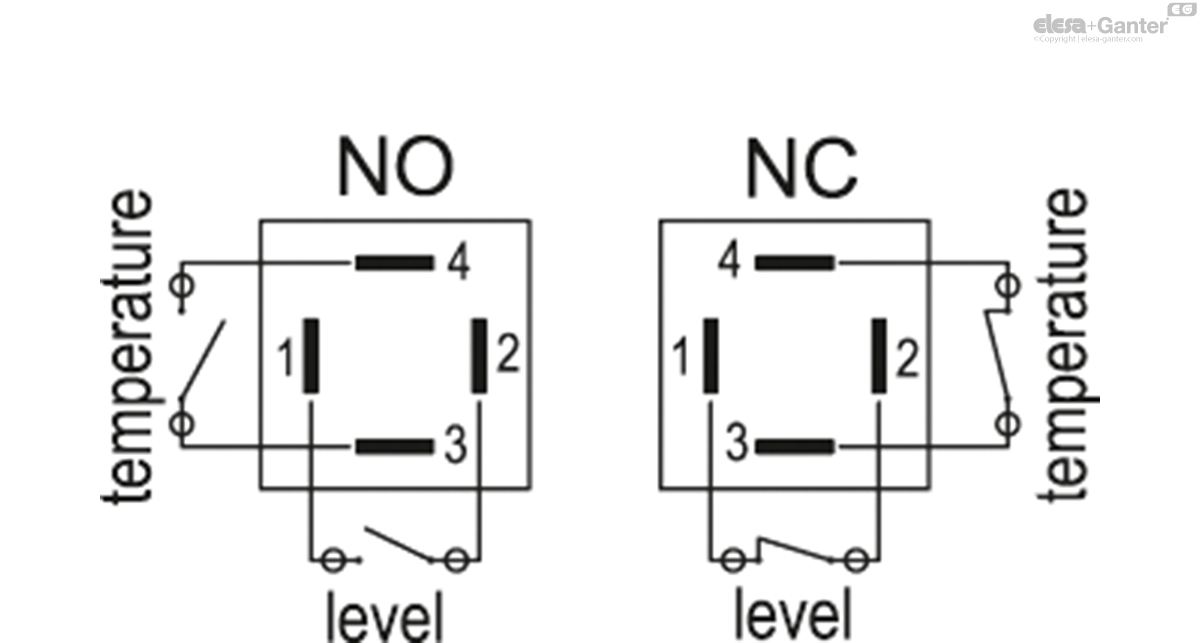
Two-pin connector assembly instructions
- Remove the connector from the indicator by unscrewing the set screw placed in the bottom, take the contact holder out and loosen the cable gland.
- Slip on the two-pole cable into the connector (standard connector) and connect the wires to the terminals nr. 1 and nr. 2 of the contact holder.
- Assemble by pressing the contact holder into the connector in the required position.
- Screw the connectors to the indicator and then tighten the cable glands.
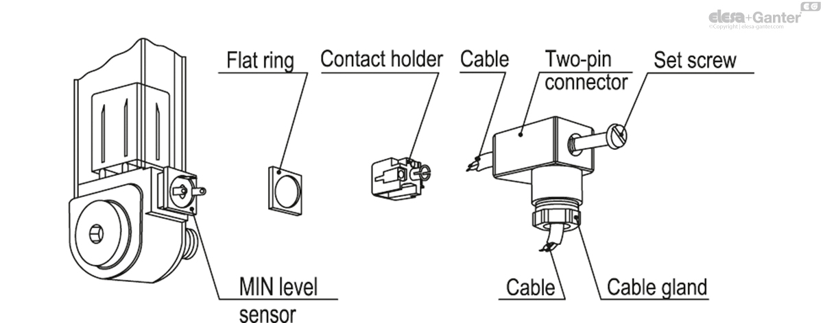
| f | d | A | B | C | H | L | e | h1 | l | l1 | m | r | d'-0.2 | f'±0.2 | C# [Nm] |
||||
|---|---|---|---|---|---|---|---|---|---|---|---|---|---|---|---|---|---|---|---|
| Code | Description | Actions | |||||||||||||||||
| 111151 | HCY.76-E-ST-NO-M12 | 76 | M12 | 22 | 29 | 32 | 46 | 108 | 41 | 37 | 40 | 17 | 16 | 20 | 10.5 | 76 | 12 | 185 |
|
| 111152 | HCY.76-E-ST-NC-M12 | 76 | M12 | 22 | 29 | 32 | 46 | 108 | 41 | 37 | 40 | 17 | 16 | 20 | 10.5 | 76 | 12 | 174 |
|
| 111161 | HCY.127-E-ST-NO-M12 | 127 | M12 | 22 | 29 | 32 | 46 | 159 | 93 | 37 | 40 | 29 | 16 | 20 | 12.5 | 127 | 12 | 210 |
|
| 111162 | HCY.127-E-ST-NC-M12 | 127 | M12 | 22 | 29 | 32 | 46 | 159 | 93 | 37 | 40 | 29 | 16 | 20 | 12.5 | 127 | 12 | 211 |
|
| 111171 | HCY.254-E-ST-NO-M12 | 254 | M12 | 22 | 29 | 32 | 46 | 286 | 219 | 37 | 40 | 29 | 16 | 20 | 12.5 | 254 | 10 | 272 |
|
| 111172 | HCY.254-E-ST-NC-M12 | 254 | M12 | 22 | 29 | 32 | 46 | 286 | 219 | 37 | 40 | 29 | 16 | 20 | 12.5 | 254 | 10 | 240 |
|

Enquiry Now
To allow us to respond to your enquiry promptly, please provide all required information.