

GN 864
Power Clamps
Steel, Pneumatic
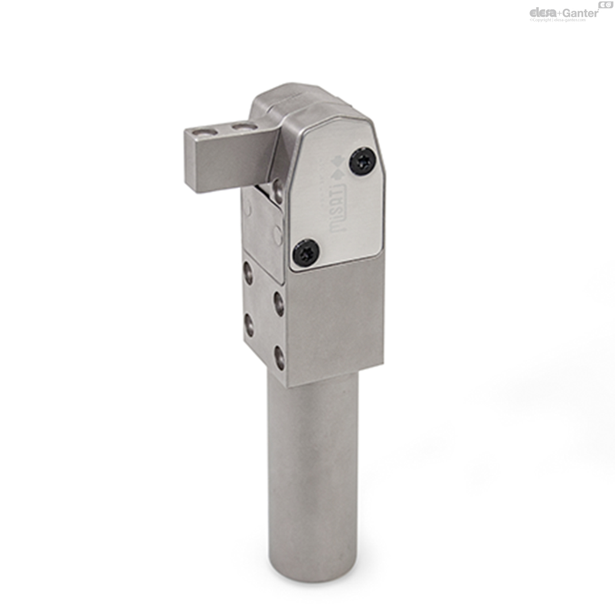
GN 864-NC
Power Clamps
Chemically nickel plated
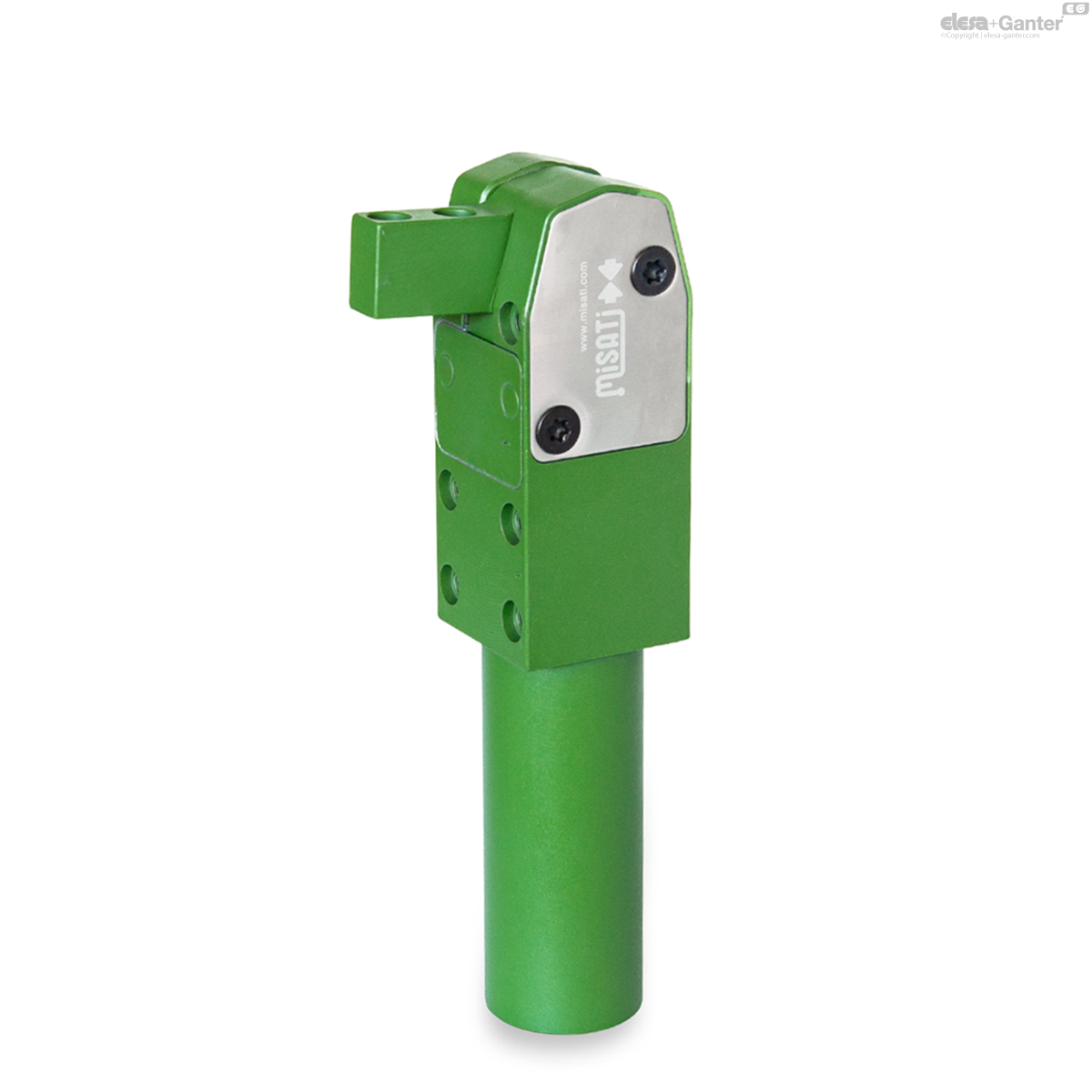
GN 864-FG
Power Clamps
Polytetrafluorethylene (PTFE), green
Description
Specification
Type
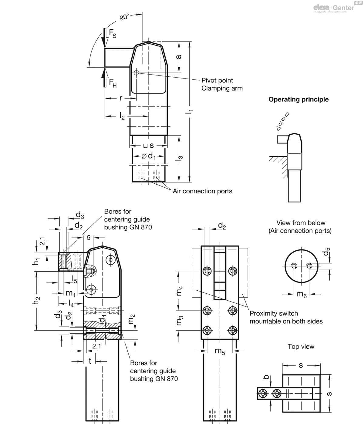
Type BL: Clamping arm horizontal
Steel C45
- Chemically nickel plated NC
- Anti-stick coating
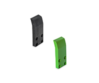
Polytetrafluorethylene (PTFE), green FG
Max. pressure 10 bar
Information
The maximum clamping moment of the power clamps GN 864 is reached once the clamping arm is at the end of its stroke. For this reason the working stroke should be completed as closely as possible to the stroke end.
The type FG is equipped with an anti-stick coating of polytetrafluorethylene (PTFE) for protection against welding spray and corrosion. With protective covers GN 864.1 the tensioning mechanism can be additionally protected against penetrating dirt.
- Information for pneumatic fastening clamps
Accessory
- Protective covers GN 864.1
Technical information
- ISO-Fundamental Tolerances
- Plastic Characteristics
- List of pneumatic clamps
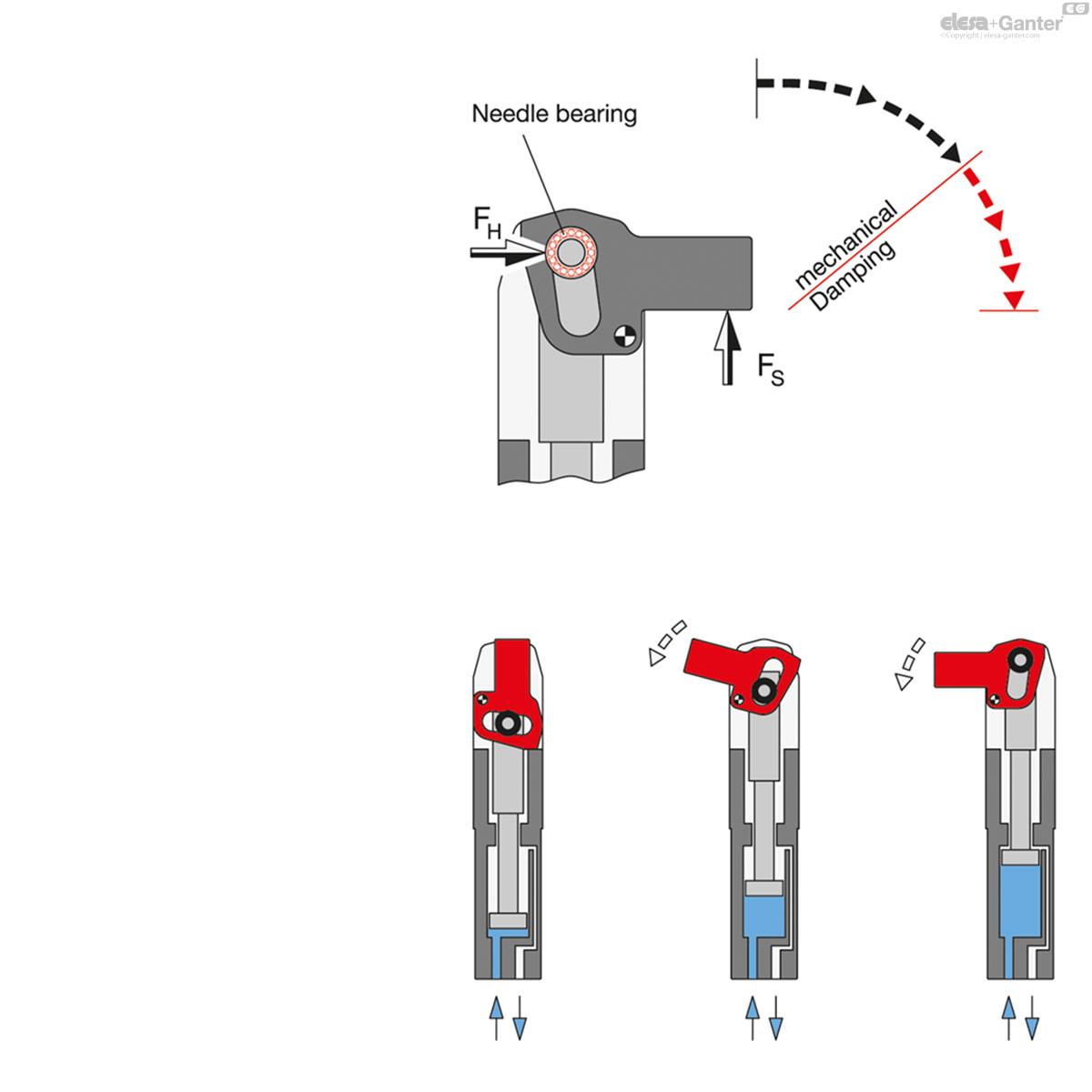
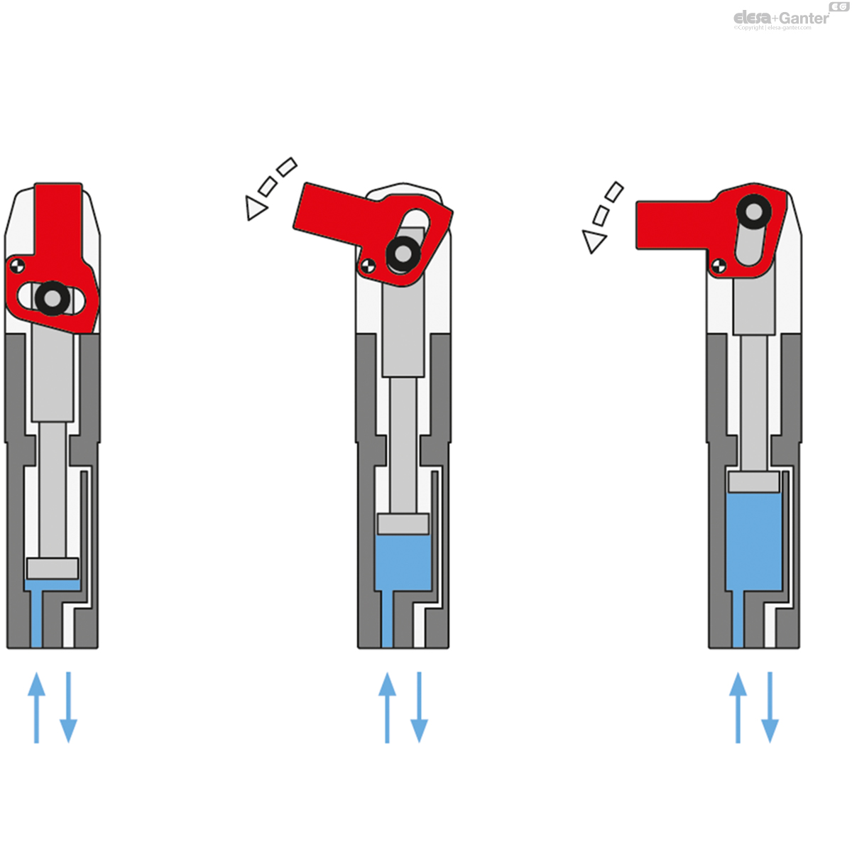
Operating principle dead point mechanism
These pneumatically operated power clamps (Patent MISATI) are used for clamping, holding, gripping and positioning of work pieces in jigs and handling systems.
The salient points of these power clamps are:
- the high clamping force
- the small dimensions
- the reduced air consumption
- the light weight
The drawings shown here explain the functional principle of the dead point mechanism.
Pistons with diameters of 20, 32, 40 and 50 mm yield a clamping force of 60 Nm up to 475 Nm, which leads to clamping forces being much above those of competitors’ power clamps.
The power clamps have been designed and configured to achieve an extended life. Functional tests have proved that even after 20 million cycles they were still serviceable.
Further salient design points are:
- The clamp is kinematically designed such that self-retention (holding force FH) is achieved in the clamped position (clamping force FS) after passing the dead point due to irreversibility.
- The forward stroke sequence of the clamping arm is rapid but the ultimate clamping action is slow and as a result pneumatic damping is normally not required. Upon request, however, it can be supplied when big masses are moved.
- The clamping mechanism is fitted with needle bearings which give optimum clamping forces and reduced wear.
- The steel cylinder with the integrated clamping mechanism are in one unit. This leads to high stability for these small units with an extended range of applications. The placement of the air connection at the bottom end leads also to many other advantages.
- The clamping mechanism of GN 864 is also shrouded to avoid the ingress of dirt and other objects which could interfere with the proper functioning of the clamps (such as welding operations!).
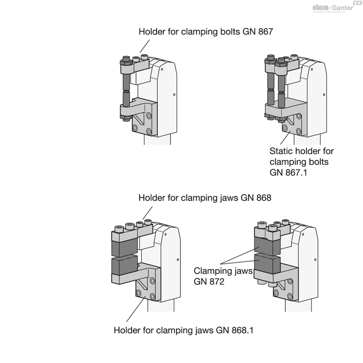
Installation examples
Principle of operation
GN 864-FG
| Size | max. clamping moment in Nm at 6 bar |
FS in N Clamping force at r at 6 bar |
FH Holding capacity at r | a | b -0.2 | d1 h8 | d2 | d3 H8 | d4 | d5 | h1 | h2 | l1 -0.5 | l2 | l3 | l4 | l5 | m1 ±0.01 | m2 | m3 ±0.01 | m4 | m5 ±0.01 | m6 | r | s | t | |||
|---|---|---|---|---|---|---|---|---|---|---|---|---|---|---|---|---|---|---|---|---|---|---|---|---|---|---|---|---|---|
| Code | Actions | ||||||||||||||||||||||||||||
| GN 864-20-BL-FG | 20 | 60 | 2220 | 7030 | 27 | 10 | 28 | M 5 | 7 | 4.2 | M 5 | 16 | 51 | 150 | 37.5 | 70 | 21.5 | 4.5 | 12 | 7.5 | 17 | 34 | 22 | 13 | 27 | 32 | 13 | 640 |
|
| GN 864-32-BL-FG | 32 | 150 | 4110 | 12876 | 36.5 | 12 | 40 | M 6 | 9 | 5 | G 1/8 | 21 | 75.5 | 206 | 52 | 91 | 31 | 6 | 18 | 10 | 25 | 51 | 30 | 22 | 36.5 | 42 | 15 | 1500 |
|
| GN 864-40-BL-FG | 40 | 300 | 6740 | 16943 | 44.5 | 16 | 50 | M 8 | 11 | 6.8 | G 1/8 | 26 | 91.5 | 244 | 63 | 104 | 37 | 7.5 | 22 | 13 | 30 | 62 | 37 | 25 | 44.5 | 52 | 18 | 2820 |
|
| GN 864-50-BL-FG | 50 | 475 | 9000 | 22666 | 52.5 | 18 | 60 | M 10 | 13 | 8.5 | G 1/8 | 31 | 114 | 279 | 74 | 110.5 | 43 | 8 | 27 | 12 | 47 | 71.5 | 44 | 35 | 52.5 | 62 | 21 | 3800 |
|

Enquiry Now
To allow us to respond to your enquiry promptly, please provide all required information.
Related Products
-
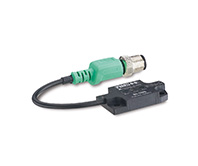 GN 893.1Proximity switchfor pneumatic fastening clamps, inductive sensorView Product
 -
 GN 864.1Protective coversfor power clamps GN 864View Product
 -
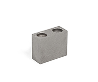 GN 872Clamping Jawsfor Power Clamps GN 864 / GN 865 / GN 866, SteelView Product
 -
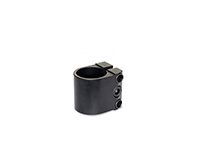 GN 873Clamp mounting bracket accessoriesfor GN 864 / GN 865 / GN 866 pneumatic fastening clampsView Product
 -
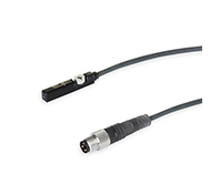 GN 3380Sensorfor Pneumatically Operated Clamps / Pneumatically Operated CylindersView Product
 -
GN 893.1Proximity switchfor pneumatic fastening clamps, inductive sensorView Product
-
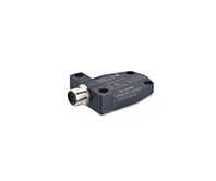 GN 893.3Proximity switchfor pneumatic fastening clamps, inductive sensorView Product
 -
 GN 893.2Proximity switchfor pneumatic fastening clamps, inductive sensorView Product
 -
GN 893.3Proximity switchfor pneumatic fastening clamps, inductive sensorView Product
-
GN 893.2Proximity switchfor pneumatic fastening clamps, inductive sensorView Product

