GN 8330
Toggle latches
Steel / Stainless Steel
Description
Specification
Types
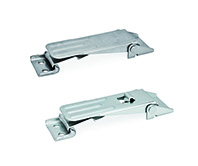
- Type A: without spring cotter pin
- Type B: with spring cotter pin
Version in Steel ST
zinc plated, blue passivated
Version in Stainless Steel NI
AISI 304
Information
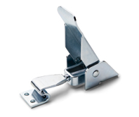
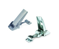
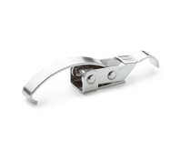
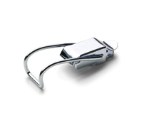
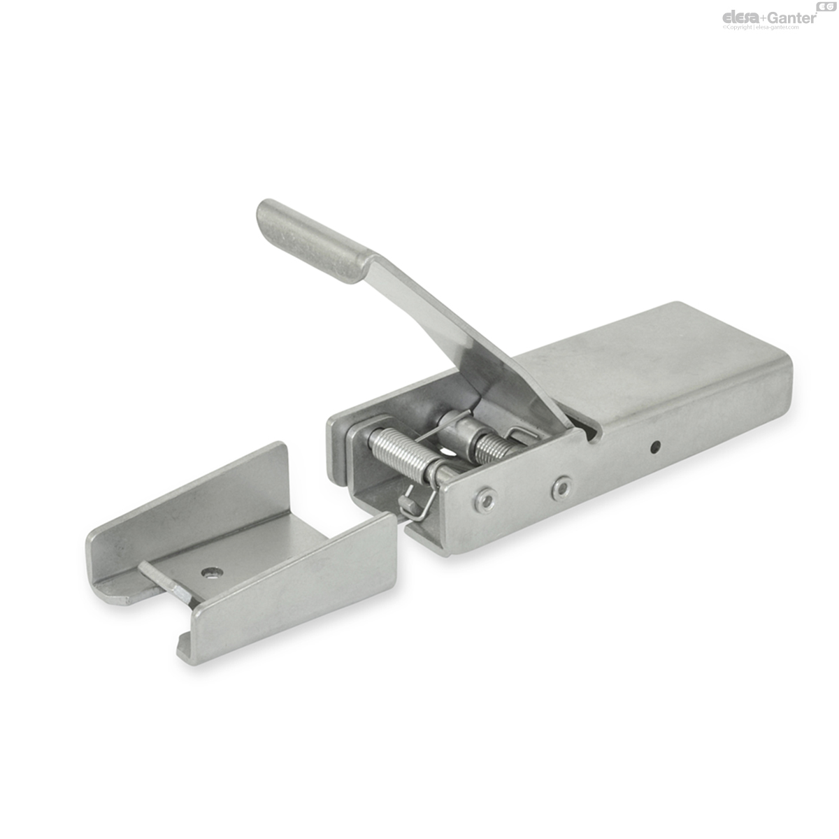
The outstanding features of GN 8330 toggle latches are superior functionality and design. The integrated spring mechanism holds the locking lever and the clamping hook in the open position and allows effortless operation.
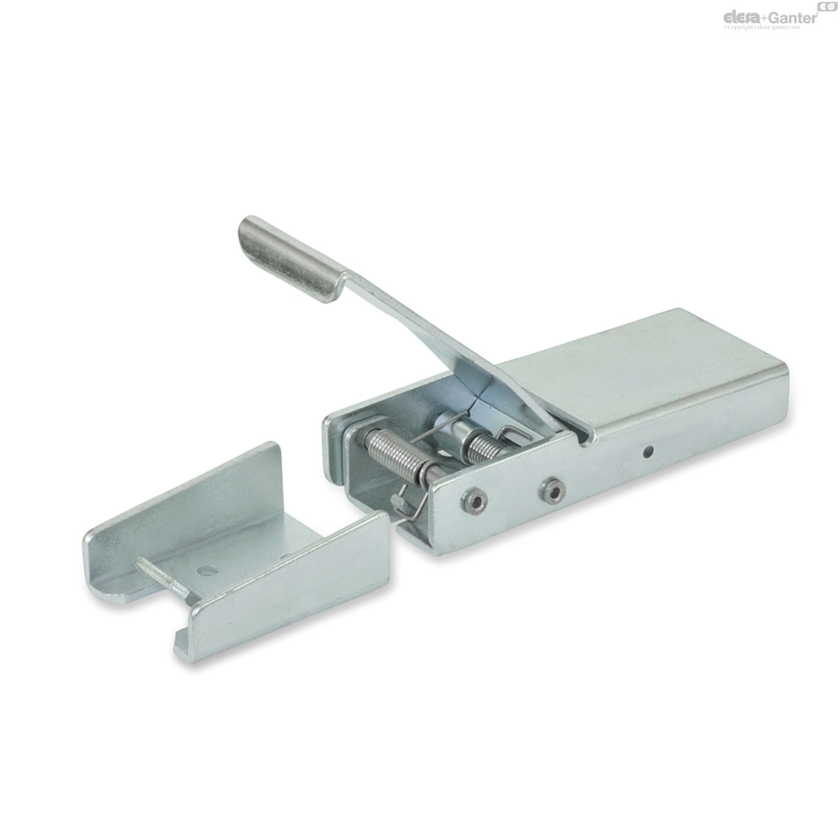
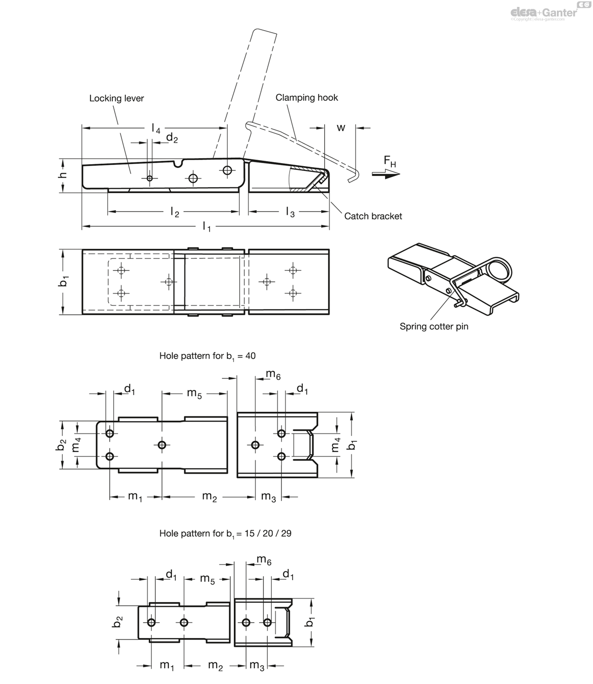
Once the dead center is exceeded, the elasticity of the sheet metal parts will cause the toggle latch to close. In the clamped position, the required drill hole spacing is m2.
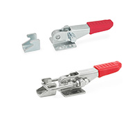
With the stroke w of the clamping hook, the elements to be connected can be pulled together during clamping.
The toggle latch can be secured against opening inadvertently with the so-called spring cotter pin. The spring cotter pin is placed into the d2 bore hole. Sealing is also possible via d2.
The retaining force given in the table is a guide value for the potentially static tensile stress load acting on the toggle latch. Depending on the conditions of use (e.g. when exposed to vibrations or shock impact), the retaining force may be impaired.
Screws with low-lying flat head must be used to guarantee the proper function. The drill template also allows the assembly using blank rivets.
On Request
- GN 8330.1 spring cotter pin
Technical Information
- Stainless Steel characteristics
Description of function
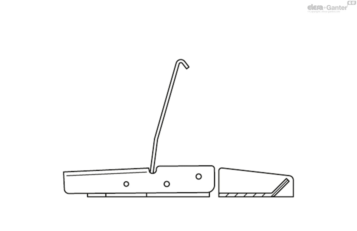
If not operated (i.e. not in the clamping position), both the locking lever and the clamping hook are held in the position shown, kept in place by two torsion springs.
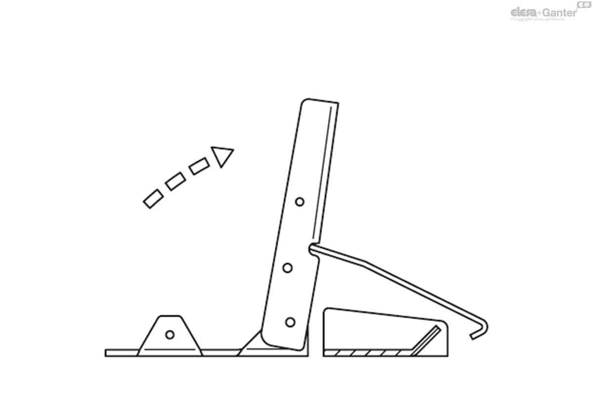
Lifting the clamping lever will swivel the clamping hook into the level of the catch bracket.
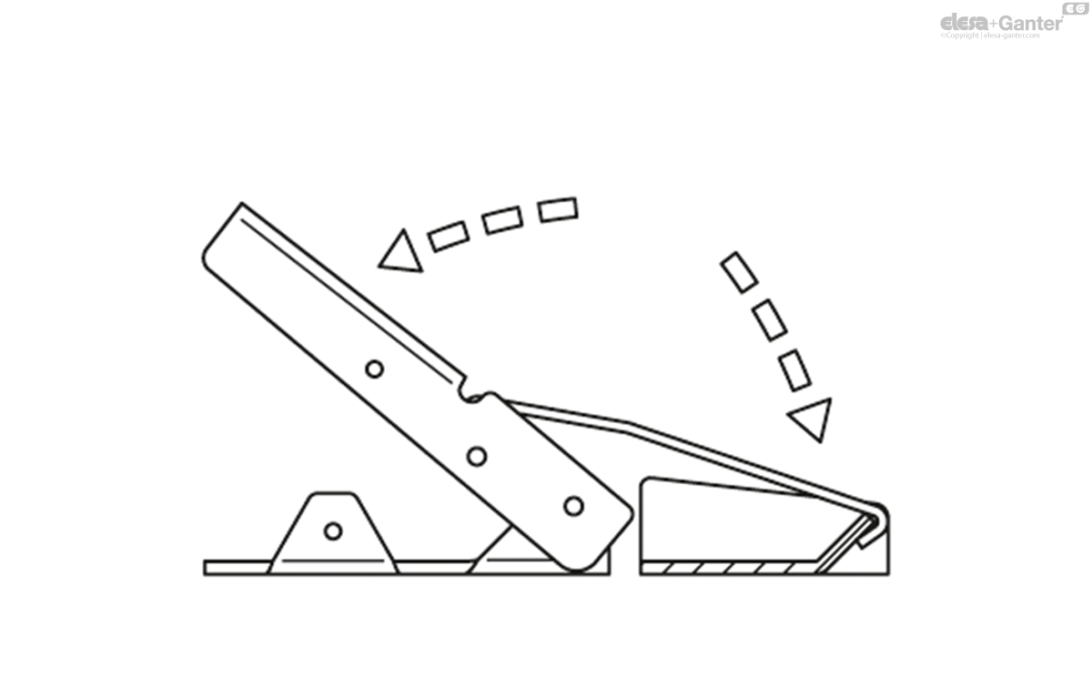
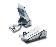
For the clamping action, the clamping hook is pressed into the catch bracket and the locking lever is at the same time turned into the starting (retaining) position.
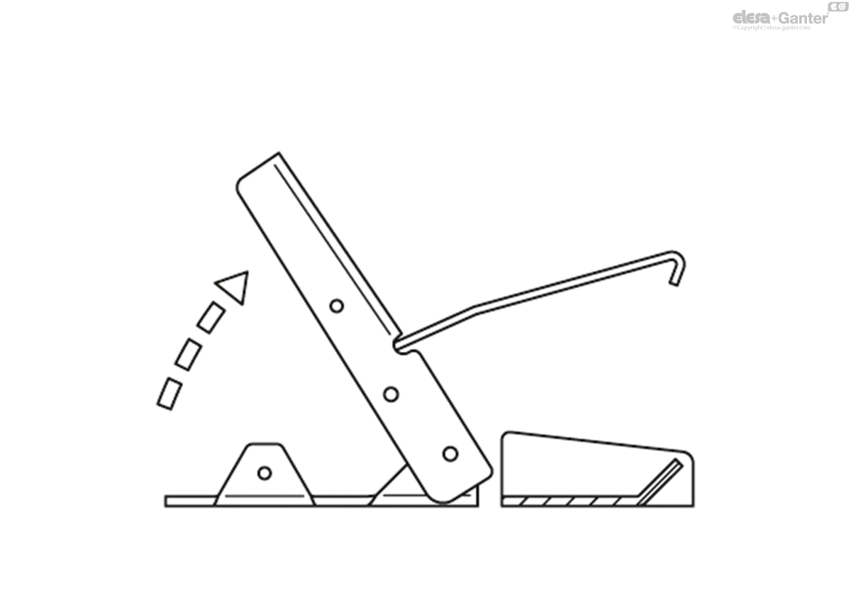
To release, simply lift the locking lever.
GN 8330
| b1 | FH in N | b2 | d1 | d2 | h | l1 ≈ | l2 | l3 | l4 | m1 | m2 | m3 | m4 | m5 | m6 | w ≈ | |||
|---|---|---|---|---|---|---|---|---|---|---|---|---|---|---|---|---|---|---|---|
| Code | Actions | ||||||||||||||||||
| GN 8330-15-ST-A | 15 | 100 | 9.5 | 3.4 | 1.4 | 8 | 53 | 25 | 17 | 31.5 | 9.5 | 13.5 | 6.2 | - | 8.5 | 3 | 11 | 16 |
|
| GN 8330-15-ST-B | 15 | 100 | 9.5 | 3.4 | 1.4 | 8 | 53 | 25 | 17 | 31.5 | 9.5 | 13.5 | 6.2 | - | 8.5 | 3 | 11 | 17 |
|
| GN 8330-20-ST-A | 20 | 300 | 13 | 3.4 | 1.8 | 10 | 76 | 34 | 25 | 44 | 8 | 29 | 8 | - | 22 | 4 | 9 | 36 |
|
| GN 8330-20-ST-B | 20 | 300 | 13 | 3.4 | 1.8 | 10 | 76 | 34 | 25 | 44 | 8 | 29 | 8 | - | 22 | 4 | 9 | 37 |
|
| GN 8330-29-ST-A | 29 | 600 | 20 | 4.2 | 2.5 | 15 | 111 | 56 | 35 | 67 | 20 | 38.8 | 13 | - | 28 | 7 | 11 | 124 |
|
| GN 8330-29-ST-B | 29 | 600 | 20 | 4.2 | 2.5 | 15 | 111 | 56 | 35 | 67 | 20 | 38.8 | 13 | - | 28 | 7 | 11 | 128 |
|
| GN 8330-40-ST-A | 40 | 1200 | 29 | 4.2 | 3 | 20 | 152 | 80 | 49 | 89 | 32 | 57.3 | 16 | 14 | 40 | 11 | 19 | 289 |
|
| GN 8330-40-ST-B | 40 | 1200 | 29 | 4.2 | 3 | 20 | 152 | 80 | 49 | 89 | 32 | 57.3 | 16 | 14 | 40 | 11 | 19 | 295 |
|

Enquiry Now
To allow us to respond to your enquiry promptly, please provide all required information.
Related Products
-
 TLN.Adjustable hook clampsSteelView Product
 -
GN 821Toggle latchesSteel / Stainless SteelView Product
-
GN 851Horizontal latch type toggle clampsSteel / Stainless Steel, for pulling actionView Product
-
GN 831Toggle latchesSteel / Stainless SteelView Product
-
TLI.Hook clampsSteel or stainless steelView Product
-
TLP.Adjustable hook clampsSteelView Product
-
TLM.Adjustable hook clampsSteel or stainless steelView Product