

GN 824
Indexing Plungers
Stainless Steel, with Chamfered Pin, with and without Rest Position
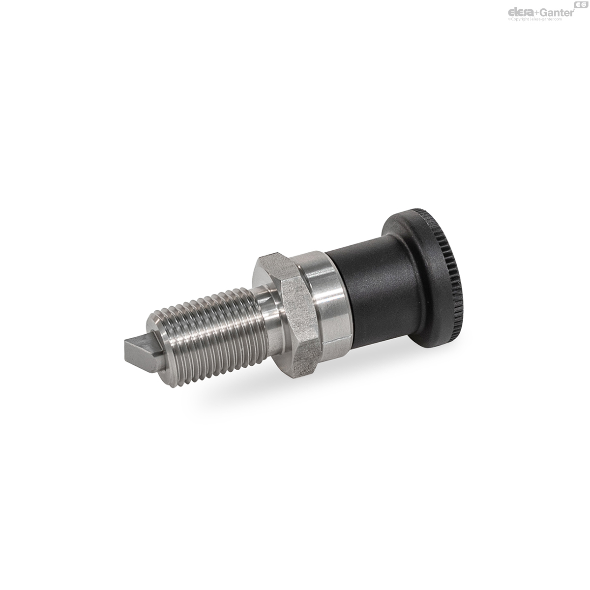
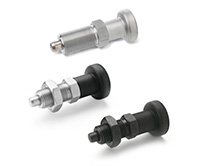
GN 824-B
Indexing Plungers
Without rest position, without lock nut
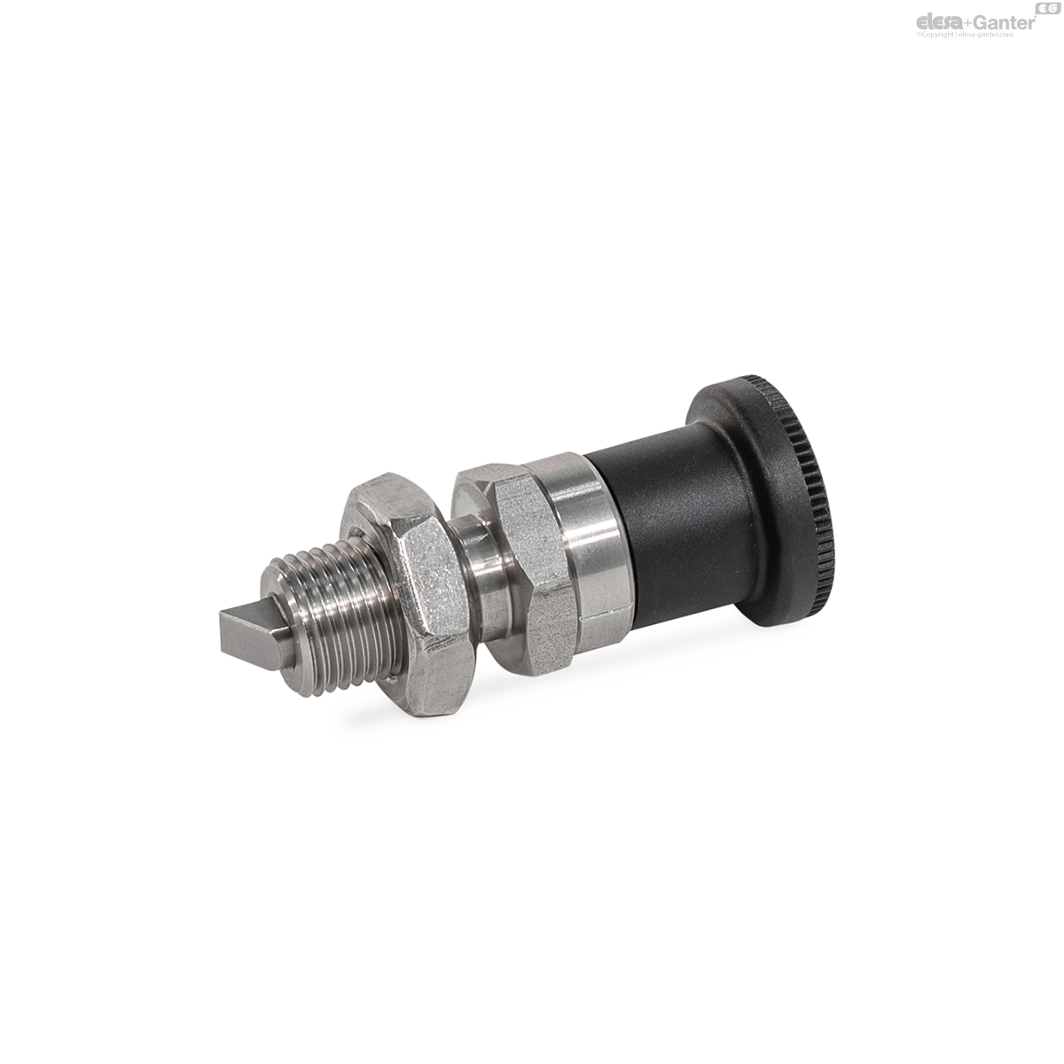
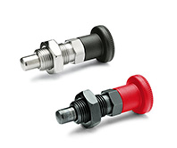
GN 824-BK
Indexing Plungers
Without rest position, with lock nut
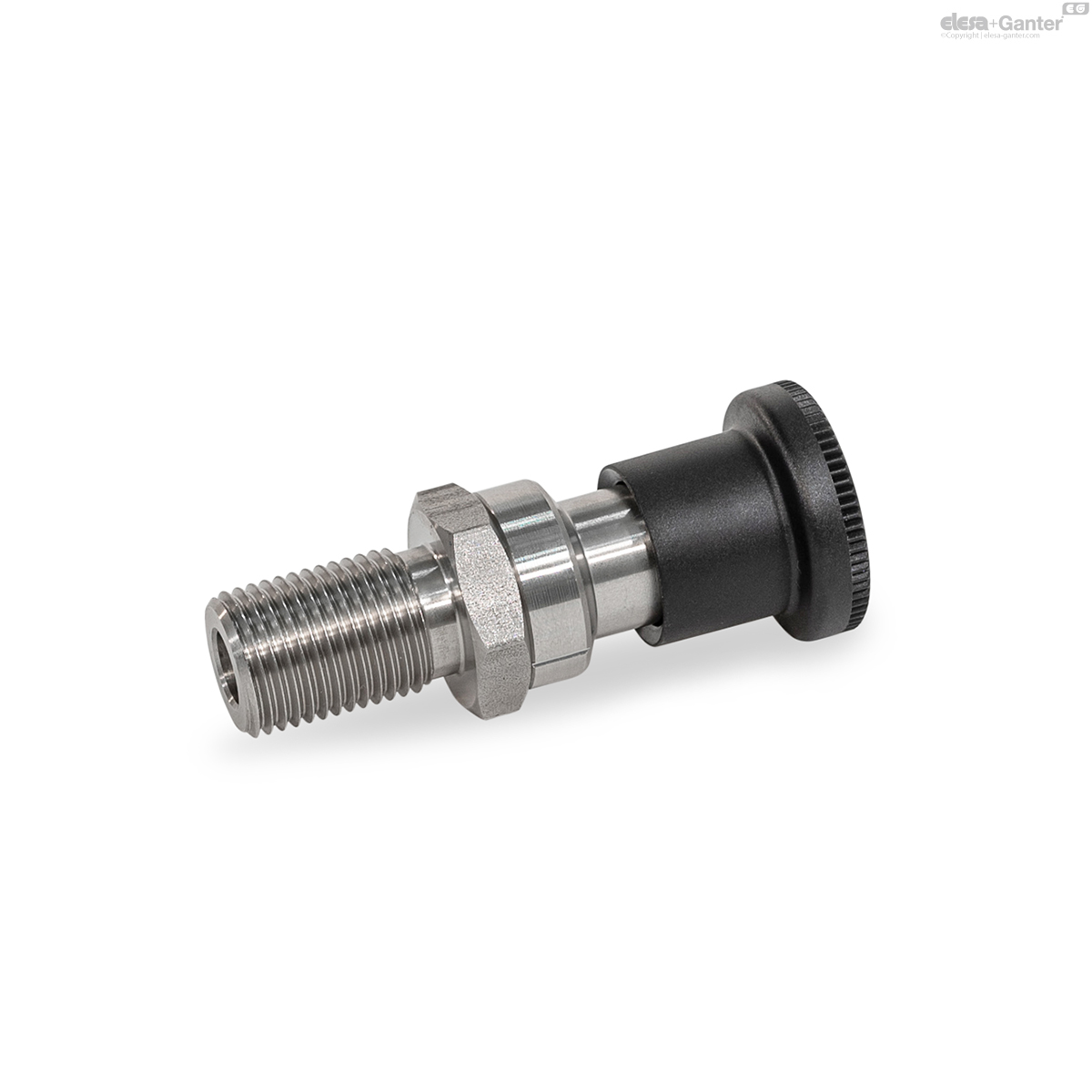
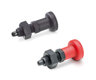
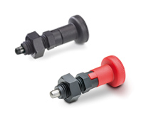
GN 824-C
Indexing Plungers
With rest position, without lock nut
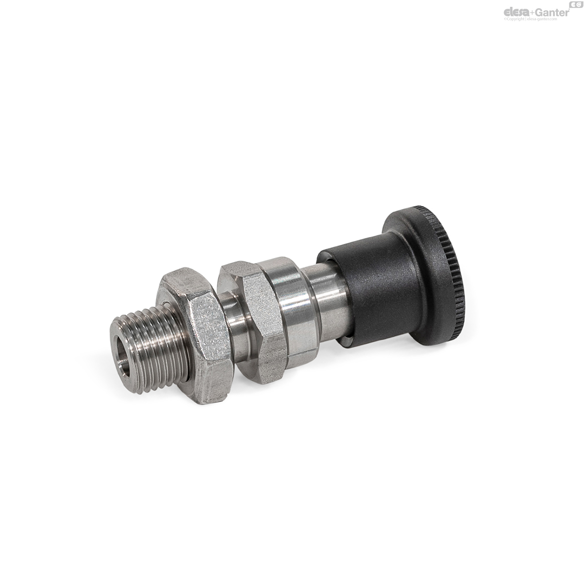
GN 824-CK
Indexing Plungers
With rest position, with lock nut
Description
Specification
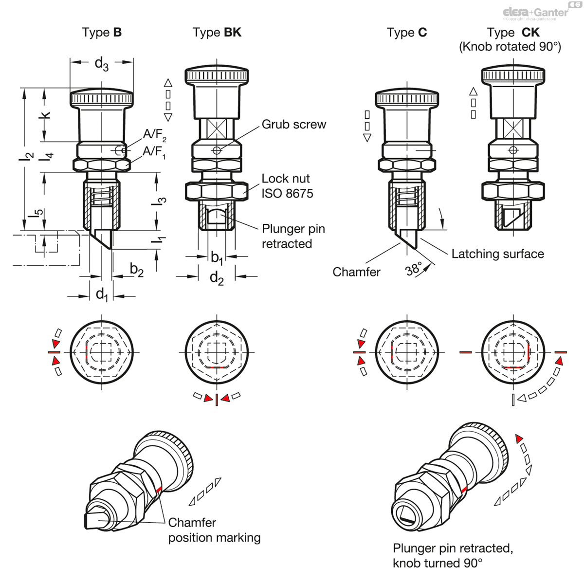
Types
- Type B: Without rest position, without lock nut
- Type BK: Without rest position, with lock nut
- Type C: With rest position, without lock nut
- Type CK: With rest position, with lock nut
Guide
Stainless steel AISI 303 NI
Plunger pin
Stainless steel AISI 431, hardened
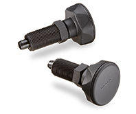
Knob
Plastic (Polyamide PA)
- Black, matte finish
- Not removable
Grub screw DIN 916
Stainless steel AISI 304
Compression spring
Stainless steel AISI 301
Hex nut ISO 8675
Stainless steel AISI 304
Information
Indexing plungers GN 824 have a plunger pin with square cross-section, a latching surface on one side and a chamfer on the other. When moving in the direction of the chamfered pin, the plunger pin passes over grooves and edges, as the chamfered pin moves the plunger pin into the guide. The plunger pin automatically latches into place when moved toward the latching surface. The latching can be released by pulling the knob.
Type C / CK indexing plungers with rest position are used for applications when the plunger pin is temporarily not to engage. In that case, the knob is retracted and afterwards turned by 90°. A notch keeps the plunger in this position.
When the grub screw is not tightened, the orientation of the bevel can be freely adjusted over a range of 360°. This can be identified by the marking on the indexing plunger guide.
- Range of indexing plungers
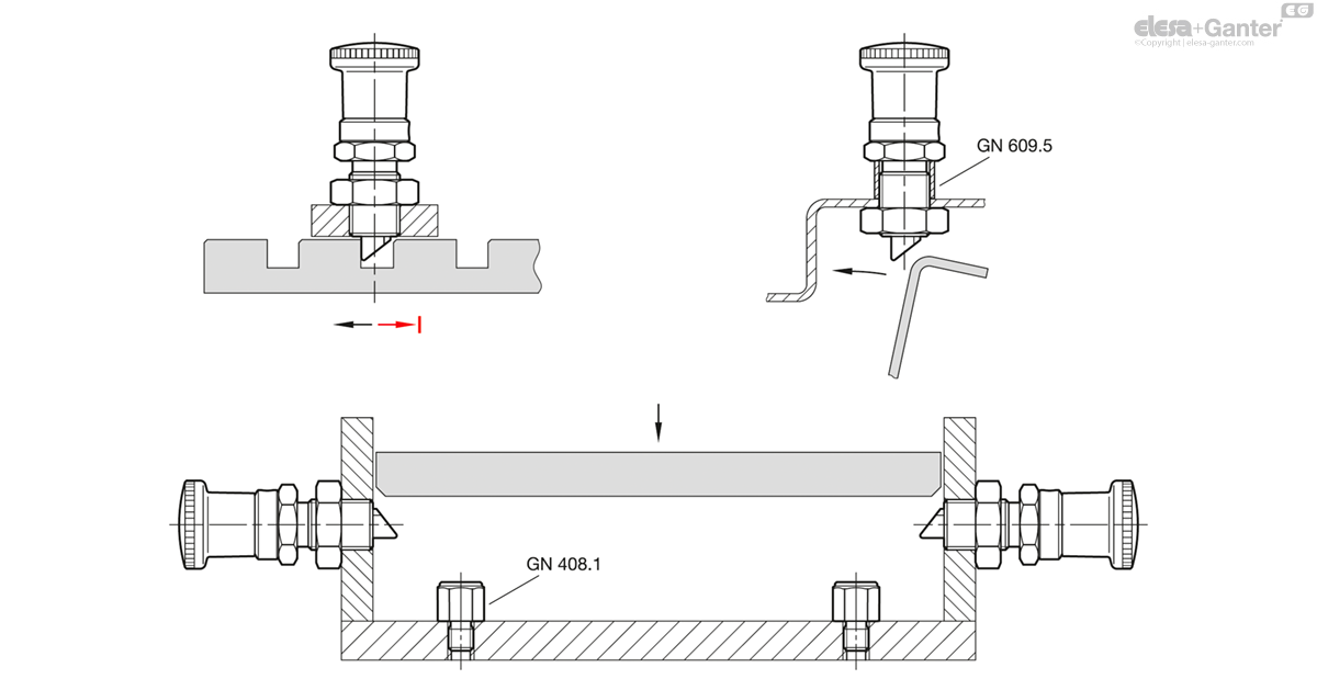
Accessory
- Distance Bushings GN 609.5
Technical information
- ISO-Fundamental Tolerances
- Plastic Characteristics
- Stainless Steel Characteristics
Assembly Instruction
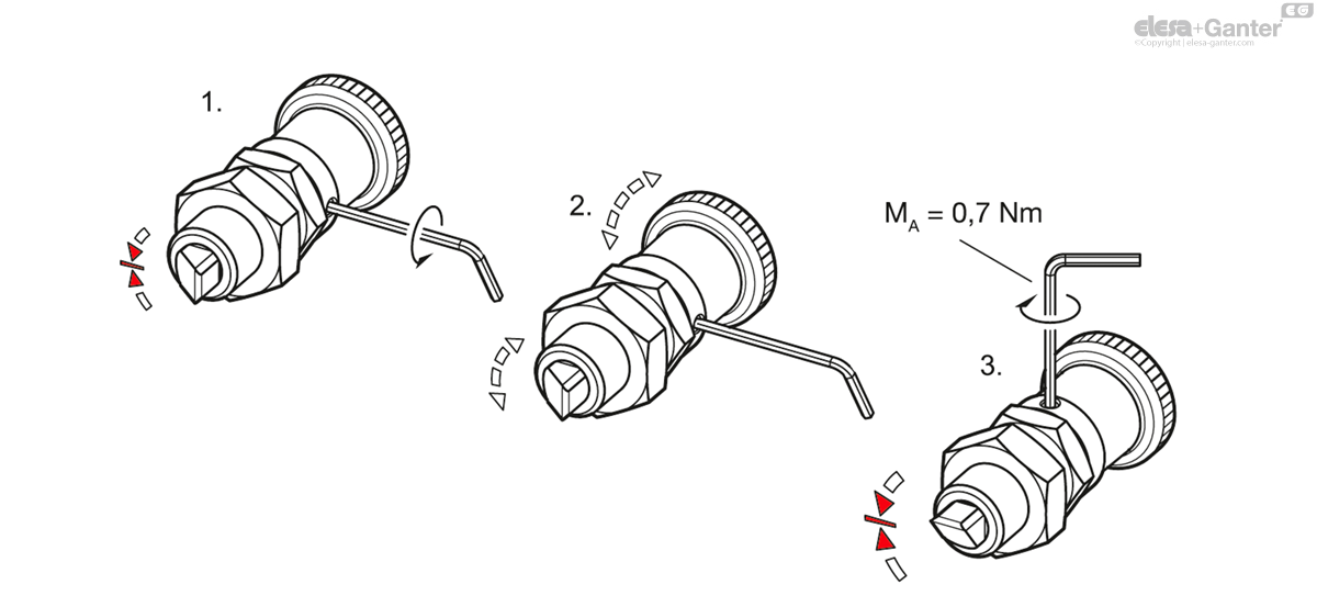
The position of the latching surface can be freely adjusted by 360°.
Installation steps:
- 1. Loosen the grub screw with a hex key.
- 2. Turn the knob to move the latching surface in the desired position.
- 3. Tighten the grub screw with a hex key.
Application Examples
GN 824-BK
| b1 | l1 | b2 | d1 Plunger -0.02/-0.04 Bore H8 |
d2 | d3 | k | l2 | l3 | l4 | l5 | A/F 1 | A/F 2 | Spring load in N≈ initial |
Spring load in N≈ end |
|||
|---|---|---|---|---|---|---|---|---|---|---|---|---|---|---|---|---|---|
| Code | Actions | ||||||||||||||||
| GN 824-5-5-BK-NI | 5 | 5 | 2.5 | 7 | M 12 x 1.5 | 23 | 20 | 51.3 | 20 | 11.3 | 1 | 17 | 2 | 9 | 18 | 56 |
|
| GN 824-6-6-BK-NI | 6 | 6 | 3 | 8 | M 16 x 1.5 | 28 | 24 | 61.5 | 24 | 13.5 | 1.2 | 22 | 2 | 13 | 23 | 116 |
|
| GN 824-8-7,5-BK-NI | 8 | 7.5 | 4 | 10 | M 16 x 1.5 | 28 | 24 | 61.5 | 24 | 13.5 | 1.2 | 22 | 2 | 15 | 31 | 75 |
|
| GN 824-9-8,5-BK-NI | 9 | 8.5 | 4.5 | 12 | M 20 x 1.5 | 33 | 28 | 72.8 | 30 | 14.8 | 1.2 | 24 | 2 | 19 | 34 | 195 |
|

Enquiry Now
To allow us to respond to your enquiry promptly, please provide all required information.
Related Products
-
 PMT.110Indexing plungersSUPER-technopolymer bodyView Product
 -
 GN 817Indexing plungersSteel / Stainless Steel, with and without rest positionView Product
 -
 GN 617Indexing plungersSteel / Stainless Steel without rest positionView Product
 -
 PMT.100Indexing plungersSUPER-technopolymer bodyView Product
 -
 PMT.101Indexing plungersRest position, SUPER-technopolymer bodyView Product

