

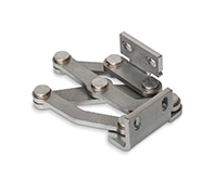
GN 7233
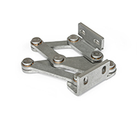
Stainless Steel-Multiple-joint hinges
concealed, opening angle 120°
GN 7233-L
Stainless Steel-Multiple-joint hinges
Fixing angle piece, left
GN 7233-R
Stainless Steel-Multiple-joint hinges
Fixing angle piece, right

Description
Specification
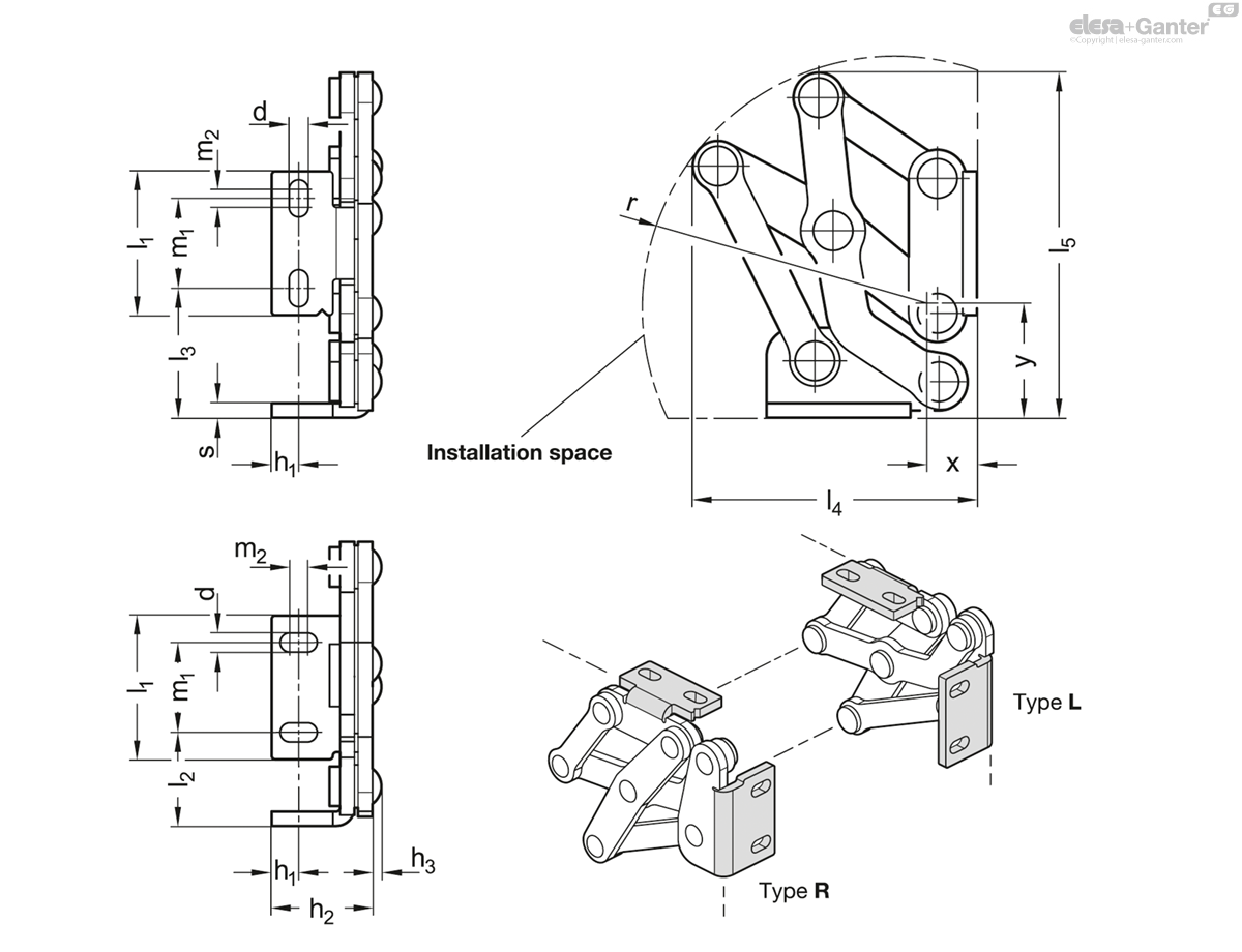
Types
- Type L: Fixing angle piece, left
- Type R: Fixing angle, piece, right
Stainless Steel 304 NI
matte, ground MT
Friction bearing
Bronze
self lubricated
Information
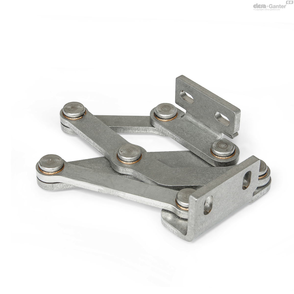
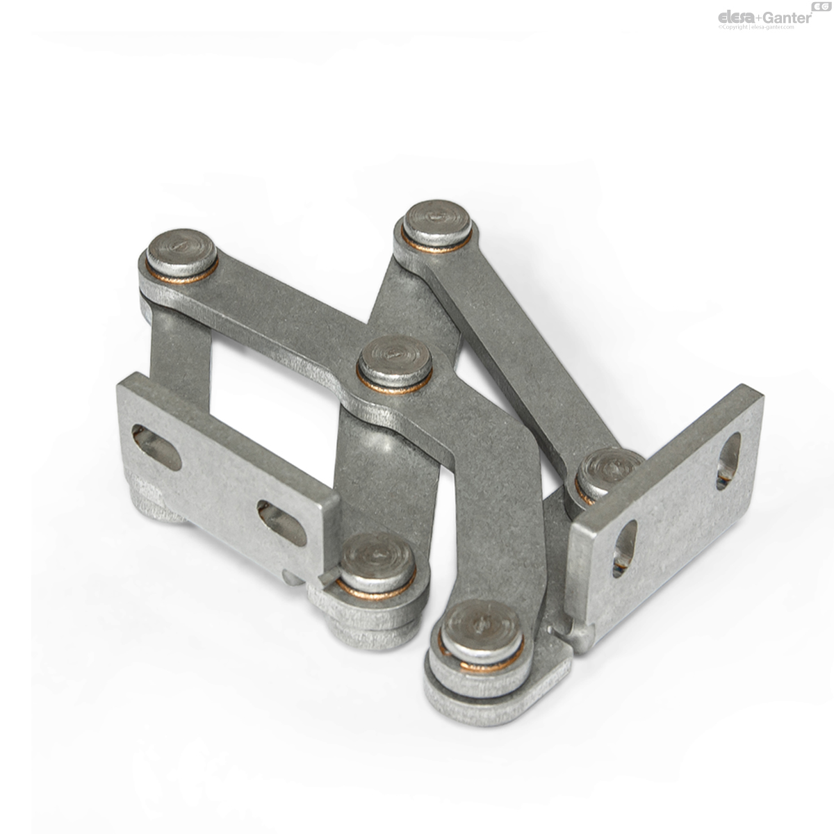
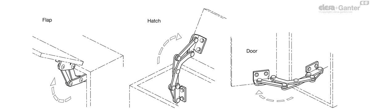
Stainless Steel-Multiple-joint hinges GN 7233 are installed on the inside of flaps, hatches and doors to save space and ensure protection against vandalism. The hinges have a maximum opening angle of 120°, allowing for easy accessibility and making them suitable for use with medium-thick doors.
Use of this hinge type leaves housing exteriors free of attachments that do not match the design or that should be avoided entirely in the interests of fast and easy cleaning.
Stainless Steel-Multiple-joint hinges are generally used in pairs, meaning that one L type and one R type are used per opening. For higher loads, e.g. from large flaps or hatches, these can be supplemented with additional hinges of any type.
On request
- other materials
- other finishes
- other fixing angle pieces
- other opening angles
- other max. wall thicknesses
- other lifting motion
Technical information
- Stainless Steel characteristics
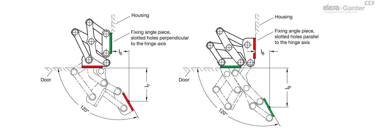
Installation position – pivot characteristics
The Stainless Steel-Multiple-joint hinges can be installed on the housing with the slots of the fixing angle piece oriented either perpendicular or parallel to the hinge axis. This results in the two pivot characteristics depicted.
Examples of use
Adjustment and fastening options
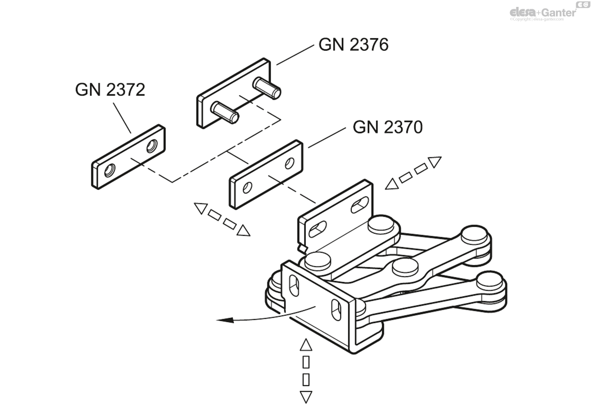
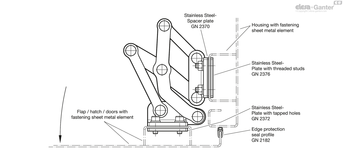
The Stainless Steel-Multiple-joint hinges can be adjusted in three planes during installation. For example, this allows tolerances to be adjusted or the required compressive forces for seals to be established.
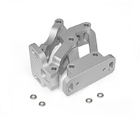
Two planes can be adjusted via the parallel or perpendicular slots in the fixing angle pieces. In the third plane, position corrections can be made using the Stainless Steel-Spacer plates GN 2370 .
Stainless Steel-Plates with tapped holes GN 2372 as well as Stainless Steel-Plates with threaded studs GN 2376 are also available for fastening the hinges. The latter can be welded on or inserted through the wall from the outside and fastened in place. All accessory items are designed for use with both fixing angle pieces.
Design variants
Flaps, hatches and doors can be inset, flush or mitered. The maximum wall thicknesses and bend sizes for sheet metal constructions given below arise from the respective installation type.
1. Fixing angle pieces mounted to the housing with slots perpendicular to the hinge axis:
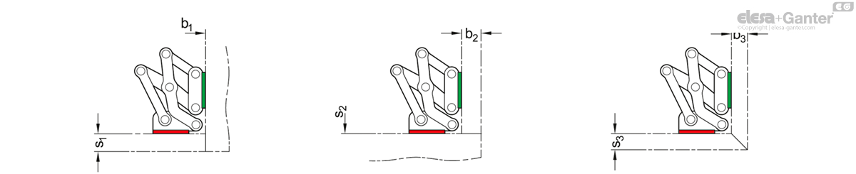
| l1 | s1 max. | b1 | s2 max. | b2 max. | s3 max. | b3 max. |
| 40 | 20 | 1 ... ∞ | 1 ... ∞ | 22 | 18 | 18 |
| 50 | 25 | 1 ... ∞ | 1 ... ∞ | 38 | 30 | 30 |
| 60 | 32 | 1 ... ∞ | 1 ... ∞ | 50 | 40 | 40 |
2. Fixing angle pieces mounted to the housing with slots parallel to the hinge axis:
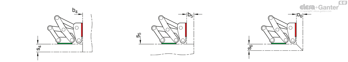
| l1 | s4 max. | b4 | s5 | b5 max. | s6 max. | b6 max. |
| 40 | 22 | 1 ... ∞ | 1 ... ∞ | 20 | 18 | 18 |
| 50 | 38 | 1 ... ∞ | 1 ... ∞ | 25 | 30 | 30 |
| 60 | 50 | 1 ... ∞ | 1 ... ∞ | 32 | 40 | 40 |
The design variants shown represent standard installation conditions. If the installation position of the hinge is changed or one of the two wall thickness dimensions is lower than s or b, the maximum achievable dimensions change independently of each other. This makes it possible in some cases to work with larger wall thickness dimensions than those specified with the same hinge size. A simple design check via CAD or a test setup is therefore recommended.
Example of an assembly
Load capacity
The maximum load of the Stainless Steel-Multiple-joint hinge specified below applies to the standard use cases and serves for orientation in the case of deviating applications. The resulting forces lead to slight elastic deformation, which can be compensated for by means of the adjustment options, if necessary.
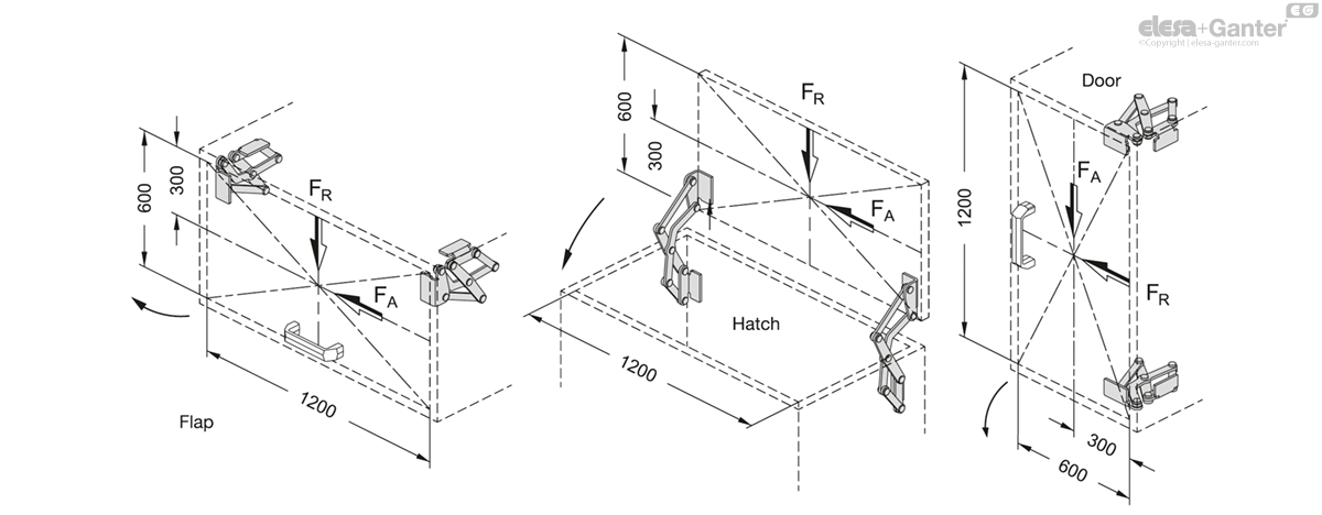
| Load capacity per hinge pair in N l1 | FA (axial) | FR (radial) |
| 40 | 175 | 650 |
| 50 | 175 | 750 |
| 60 | 150 | 550 |
GN 7233-R
| l1 | d | h1 | h2 | h3 | l2 | l3 | l4 | l5 | l6 | l7 | l8 | l9 | m1 | m2 | r | s | x | y | |||
|---|---|---|---|---|---|---|---|---|---|---|---|---|---|---|---|---|---|---|---|---|---|
| Code | Actions | ||||||||||||||||||||
| GN 7233-NI-40-R-MT | 40 | 5.3 | 7.5 | 28 | 2.5 | 26 | 36 | 79 | 96 | 33.8 | 65.9 | 27.9 | 77.4 | 25 | 5 | 70 | 4 | 23 | 30.5 | 267 |
|
| GN 7233-NI-50-R-MT | 50 | 6.5 | 10 | 35 | 2.5 | 35 | 46 | 105 | 135 | 79.3 | 82 | 2.8 | 113.3 | 30 | 6 | 105 | 5 | 20 | 37 | 533 |
|
| GN 7233-NI-60-R-MT | 60 | 8.5 | 12.5 | 40 | 2.5 | 40 | 61 | 130 | 169 | 87.5 | 107.5 | 17.4 | 147.1 | 36 | 8 | 125 | 5 | 34 | 50 | 700 |
|

Enquiry Now
To allow us to respond to your enquiry promptly, please provide all required information.
Related Products
-
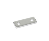 GN 2370Stainless Steel-Spacer platesfor hingesView Product
 -
 GN 7237Stainless Steel Multiple-Joint HingesConcealed, Opening Angle 180°View Product
 -
 GN 7231Stainless Steel-Multiple-joint hingesconcealed, opening angle 90°View Product
 -
 GN 7243Multiple-joint hingeconcealed, opening angle 120°View Product
 -
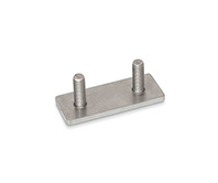 GN 2376Stainless Steel-Plateswith threaded studs, for hingesView Product
 -
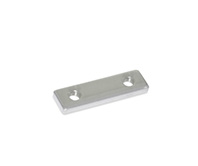 GN 2372Stainless Steel-Plateswith tapped holes, for hingesView Product

