

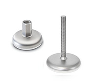
GN 41
Leveling Feet
Stainless Steel
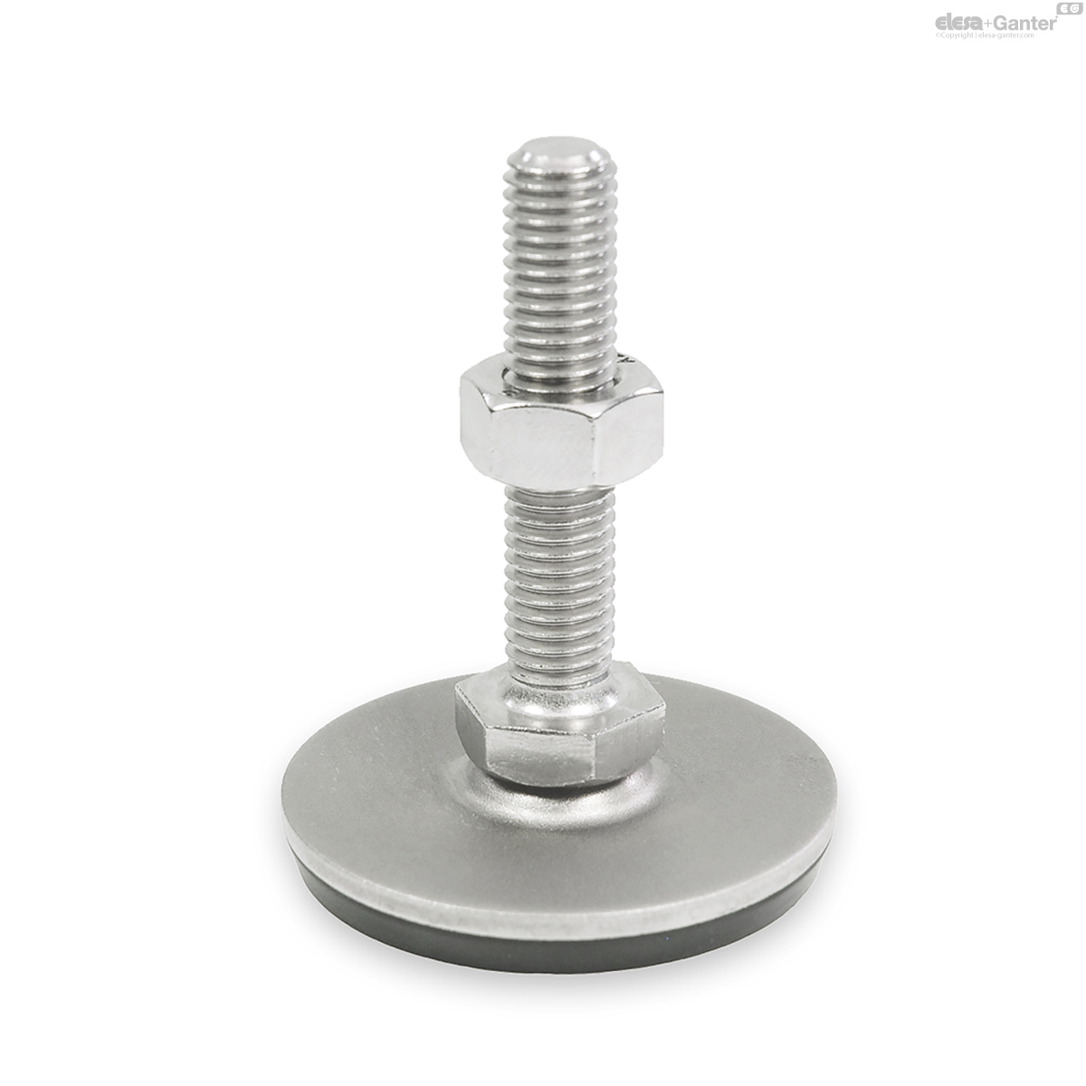
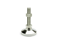
GN 41-S/SK
Leveling Feet
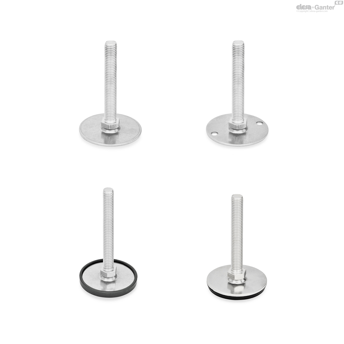
With / without nut, external hex at the bottom
GN 41-T/TK
Leveling Feet
With / without nut, wrench flat at the bottom
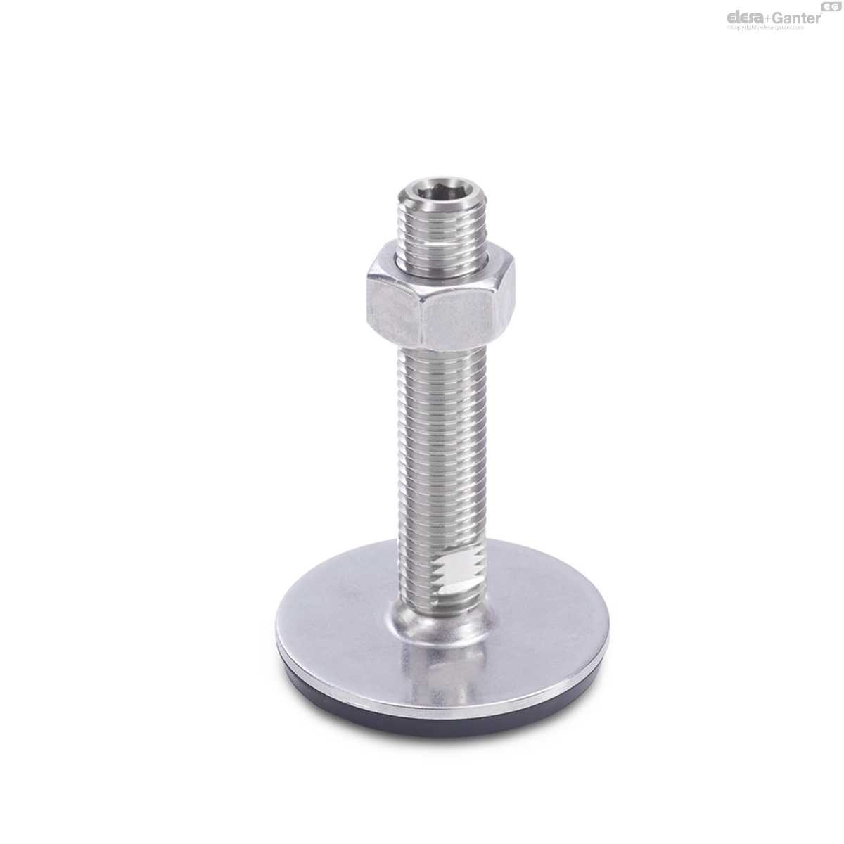
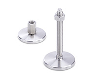
GN 41-U/UK
Leveling Feet
With / without nut, hex socket at the top and wrench flat at the bottom
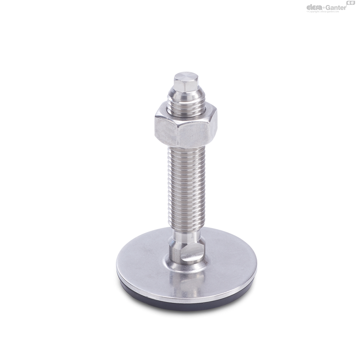
GN 41-V/VK
Leveling Feet
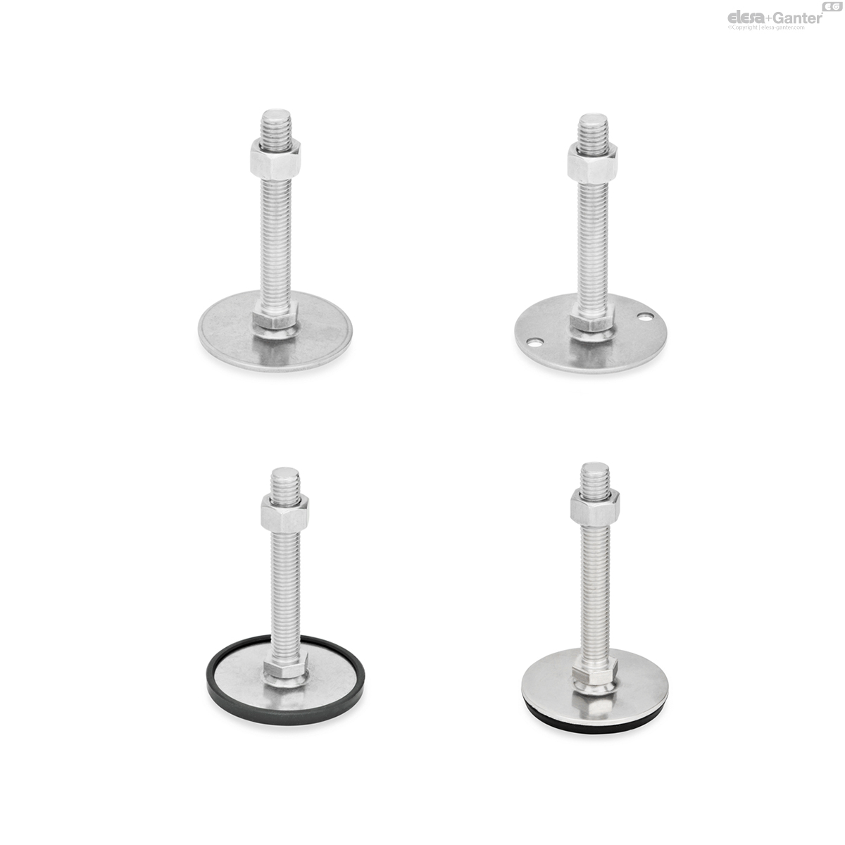
With / without nut, external hex at the top and wrench flat at the bottom
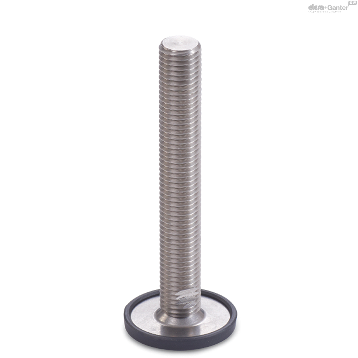
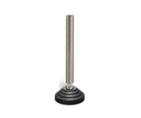
GN 41-W
Leveling Feet
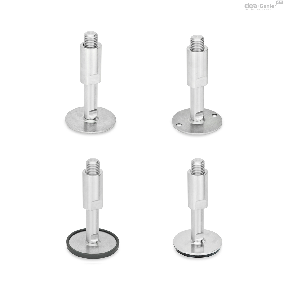
With adjustable sleeve, covered thread and wrench flat at the bottom
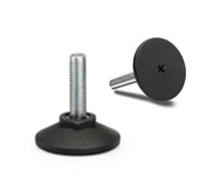
GN 41-X
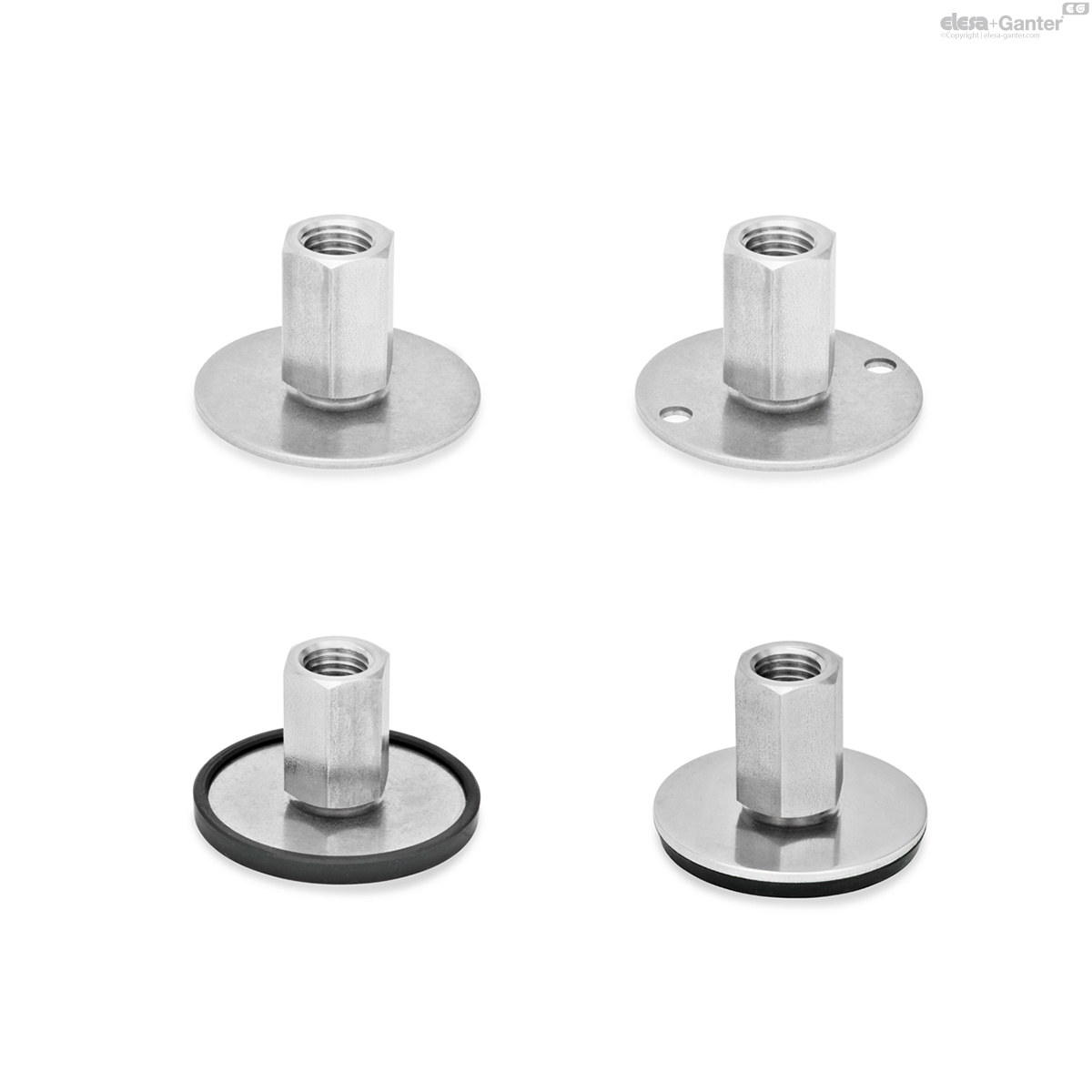
Leveling Feet
External hex with internal thread
Description
Specification
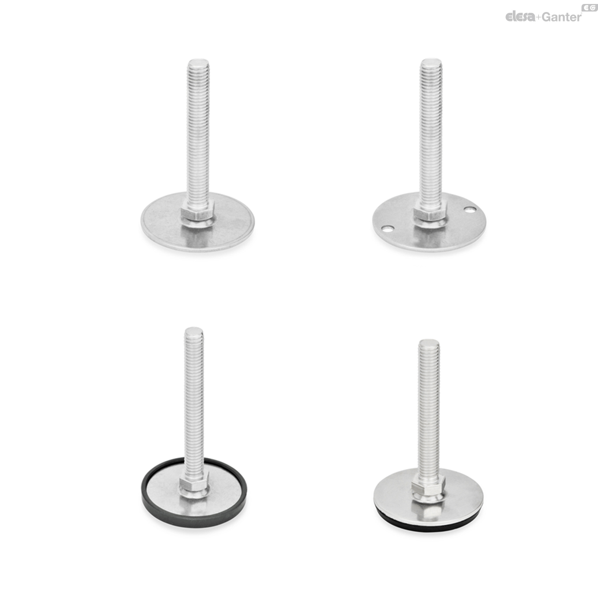
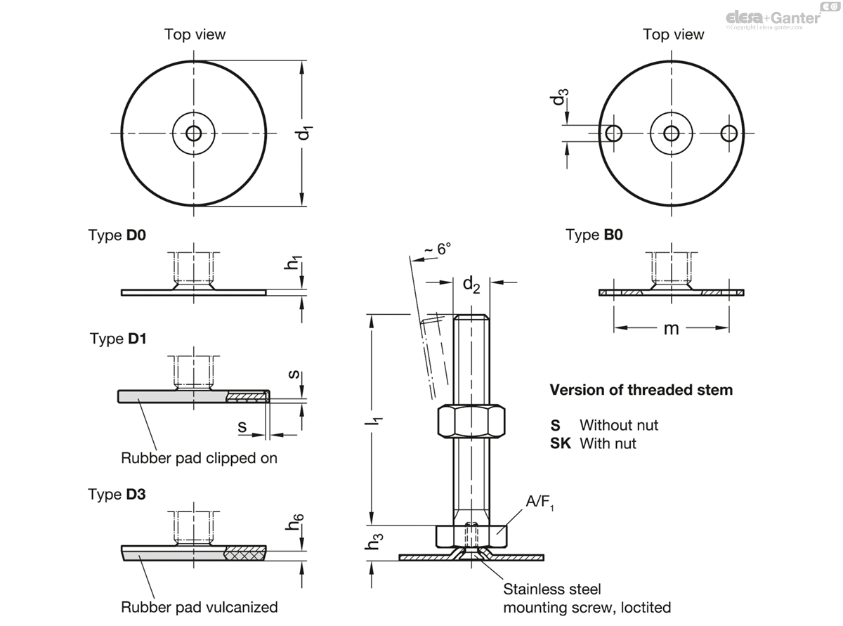
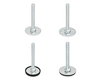
Types (Base plate)
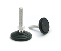
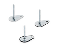
- Type D0: Without rubber pad
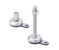
- Type B0: Without rubber pad, with 2 mounting holes
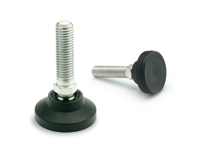
- Type D1: With rubber pad, clipped on, black
- Type D3: With rubber pad, vulcanized, black
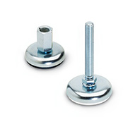
Version (Screw)
- Version S: Without nut, external hex at the bottom
- Version SK: With nut, external hex at the bottom
- Version T: Without nut, wrench flat at the bottom
- Version TK: With nut, wrench flat at the bottom
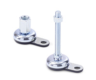
- Version U: Without nut, hex socket at the top and wrench flat at the bottom
- Version UK: With nut, hex socket at the top and wrench flat at the bottom
- Version V: Without nut, external hex at the top and wrench flat at the bottom
- Version VK: With nut, external hex at the top and wrench flat at the bottom
- Version W: With adjustable sleeve, covered thread and wrench flat at the bottom
- Version X: External hex with internal thread
Base plate
Stainless steel AISI 304
Blank ground
Threaded stem
Stainless steel AISI 303
Hex nut ISO 4032
Stainless steel
Rubber pad
Clipped on
Black, TPE (Santoprene®)
≈ 80 Shore A
Rubber pad
Vulcanized
Black, NBR (Perbunan®)
70 ± 5 Shore A
Information
Leveling feet GN 41 are for use in aggressive environments. The range of combinations of base plates and adjustable spindle versions allows these leveling feet to be used in every situation.
The base plate with the rubber pad protects sensitive surfaces and reduces lateral slippage. The type B0 can also be fastened to the mounting surface through two holes.
The leveling feet are supplied fully assembled and are not removable.
Technical information
- Plastic Characteristics
- Stainless Steel Characteristics
Load Rating of Leveling Feet
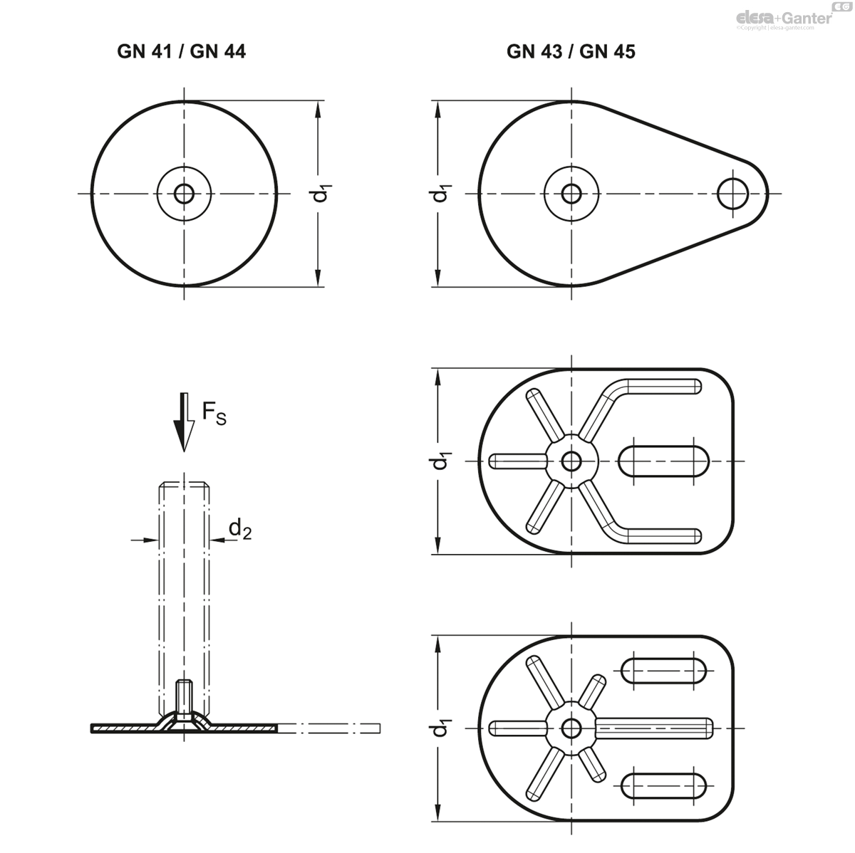
| d1 | - | - | d2 | Static load in kN | - | - | - | - |
| GN 41 / GN 44 | GN 43 / GN 45 | GN 43 | - | Versions of threaded stem | - | - | - | - |
| - | Drop shape | Rectangular shape | - | S / SK | T / TK and U / UK | V / VK | W | X |
| 40 | - | - | M 8 | 8 | - | - | - | 8 |
| 40 | - | - | M 10 | 12 | - | - | - | 12 |
| 40 | - | - | M 12 | 12 | - | - | - | 12 |
| 40 | - | - | M 16 | - | 12 | - | - | 12 |
| 50 | 50 | - | M 8 | 8 | - | - | - | 8 |
| 50 | 50 | - | M 10 | 14 | - | - | - | 14 |
| 50 | 50 | - | M 12 | 14 | - | - | - | 14 |
| 50 | 50 | - | M 16 | - | 14 | - | - | 14 |
| 60 | 60 | - | M 8 | 8 | - | - | - | 8 |
| 60 | 60 | - | M 10 | 14 | - | - | - | 14 |
| 60 | 60 | - | M 12 | 16 | - | - | - | 16 |
| 60 | 60 | - | M 16 | - | 16 | 16 | 16 | 16 |
| 80 | 80 | 80 | M 8 | 8 | - | - | - | 8 |
| 80 | 80 | 80 | M 10 | 14 | - | - | - | 14 |
| 80 | 80 | 80 | M 12 | 20 | - | - | - | 20 |
| 80 | 80 | 80 | M 16 | - | 20 | 20 | 20 | 20 |
| 80 | 80 | 80 | M 20 | - | 20 | 20 | 20 | 20 |
| 80 | 80 | 80 | M 24 | - | 22 | 22 | 22 | - |
The static load bearing capacity given in the table rests on a test series in which the load has been applied perpendicular to the base plate (without rubber underlay). For the values given in the table, the strain relief may result in minor deformations of the base plate.
Bending and buckling stress which often occurs in practice results in a lower load bearing capacity of the adjustment spindle and may have to be taken into account.
Also, the spindle strength is assumed to be ≥ 500 N/mm2.
The details given on strength are nonbinding guide values without any liability. In general, they do not constitute a warranty of quality.
The user must determine from case to case if a product is suitable for the intended purpose or use. Environmental factors may influence the stated values.
Versions of threaded stem
| Versions of threaded stem | ||
| S / SK: External hex at the bottom at d2 M 8, M 10, M 12 | T / TK: Wrench flat at the bottom at d2 M 16, M 20, M 24 | U / UK: Hex socket at the top and wrench flat at the bottom at d2 M 16, M 20, M 24 |
| V / VK: External hex at the top and wrench flat at the bottom at d2 M 16, M 20, M 24 | W: Covered thread and wrench flat at the bottom at d2 M 16, M 20, M 24 | X: External hex with internal thread at d2 M 8, M 10, M 12, M 16, M 20 |
GN 41-S/SK
| Color | d1 | d2 | l1 | d3 | h1 | h3 | h6 | m | s | A/F 1 | Static load in kN |
|||
|---|---|---|---|---|---|---|---|---|---|---|---|---|---|---|
| Code | Actions | |||||||||||||
| GN 41-40-M8-40-B0-S | Type S | 40 | M 8 | 40 | 5.4 | 2 | 11 | - | 30 | - | 17 | 8 | 139 |
|
| GN 41-40-M8-40-B0-SK | SK | 40 | M 8 | 40 | 5.4 | 2 | 11 | - | 30 | - | 17 | 8 | 143 |
|
| GN 41-40-M8-40-D0-S | Type S | 40 | M 8 | 40 | - | 2 | 11 | - | 30 | - | 17 | 8 | 41 |
|
| GN 41-40-M8-40-D0-SK | SK | 40 | M 8 | 40 | - | 2 | 11 | - | 30 | - | 17 | 8 | 45 |
|
| GN 41-40-M8-40-D1-S | Type S | 40 | M 8 | 40 | - | 2 | 11 | - | 30 | 1.5 | 17 | 8 | 44 |
|
| GN 41-40-M8-40-D1-SK | SK | 40 | M 8 | 40 | - | 2 | 11 | - | 30 | 1.5 | 17 | 8 | 48 |
|
| GN 41-40-M8-40-D3-S | Type S | 40 | M 8 | 40 | - | 2 | 11 | 3.5 | 30 | - | 17 | 8 | 43 |
|
| GN 41-40-M8-40-D3-SK | SK | 40 | M 8 | 40 | - | 2 | 11 | 3.5 | 30 | - | 17 | 8 | 46 |
|
| GN 41-40-M8-50-B0-S | Type S | 40 | M 8 | 50 | 5.4 | 2 | 11 | - | 30 | - | 17 | 8 | 142 |
|
| GN 41-40-M8-50-B0-SK | SK | 40 | M 8 | 50 | 5.4 | 2 | 11 | - | 30 | - | 17 | 8 | 146 |
|
| GN 41-40-M8-50-D0-S | Type S | 40 | M 8 | 50 | - | 2 | 11 | - | 30 | - | 17 | 8 | 44 |
|
| GN 41-40-M8-50-D0-SK | SK | 40 | M 8 | 50 | - | 2 | 11 | - | 30 | - | 17 | 8 | 48 |
|
| GN 41-40-M8-50-D1-S | Type S | 40 | M 8 | 50 | - | 2 | 11 | - | 30 | 1.5 | 17 | 8 | 47 |
|
| GN 41-40-M8-50-D1-SK | SK | 40 | M 8 | 50 | - | 2 | 11 | - | 30 | 1.5 | 17 | 8 | 51 |
|
| GN 41-40-M8-50-D3-S | Type S | 40 | M 8 | 50 | - | 2 | 11 | 3.5 | 30 | - | 17 | 8 | 45 |
|
| GN 41-40-M8-50-D3-SK | SK | 40 | M 8 | 50 | - | 2 | 11 | 3.5 | 30 | - | 17 | 8 | 49 |
|
| GN 41-40-M8-63-B0-S | Type S | 40 | M 8 | 63 | 5.4 | 2 | 11 | - | 30 | - | 17 | 8 | 147 |
|
| GN 41-40-M8-63-B0-SK | SK | 40 | M 8 | 63 | 5.4 | 2 | 11 | - | 30 | - | 17 | 8 | 151 |
|
| GN 41-40-M8-63-D0-S | Type S | 40 | M 8 | 63 | - | 2 | 11 | - | 30 | - | 17 | 8 | 49 |
|
| GN 41-40-M8-63-D0-SK | SK | 40 | M 8 | 63 | - | 2 | 11 | - | 30 | - | 17 | 8 | 53 |
|
| GN 41-40-M8-63-D1-S | Type S | 40 | M 8 | 63 | - | 2 | 11 | - | 30 | 1.5 | 17 | 8 | 52 |
|
| GN 41-40-M8-63-D1-SK | SK | 40 | M 8 | 63 | - | 2 | 11 | - | 30 | 1.5 | 17 | 8 | 56 |
|
| GN 41-40-M8-63-D3-S | Type S | 40 | M 8 | 63 | - | 2 | 11 | 3.5 | 30 | - | 17 | 8 | 50 |
|
| GN 41-40-M8-63-D3-SK | SK | 40 | M 8 | 63 | - | 2 | 11 | 3.5 | 30 | - | 17 | 8 | 54 |
|
| GN 41-40-M10-50-B0-S | Type S | 40 | M 10 | 50 | 5.4 | 2 | 11 | - | 30 | - | 17 | 12 | 152 |
|
| GN 41-40-M10-50-B0-SK | SK | 40 | M 10 | 50 | 5.4 | 2 | 11 | - | 30 | - | 17 | 12 | 161 |
|
| GN 41-40-M10-50-D0-S | Type S | 40 | M 10 | 50 | - | 2 | 11 | - | 30 | - | 17 | 12 | 54 |
|
| GN 41-40-M10-50-D0-SK | SK | 40 | M 10 | 50 | - | 2 | 11 | - | 30 | - | 17 | 12 | 63 |
|
| GN 41-40-M10-50-D1-S | Type S | 40 | M 10 | 50 | - | 2 | 11 | - | 30 | 1.5 | 17 | 12 | 57 |
|
| GN 41-40-M10-50-D1-SK | SK | 40 | M 10 | 50 | - | 2 | 11 | - | 30 | 1.5 | 17 | 12 | 66 |
|
| GN 41-40-M10-50-D3-S | Type S | 40 | M 10 | 50 | - | 2 | 11 | 3.5 | 30 | - | 17 | 12 | 55 |
|
| GN 41-40-M10-50-D3-SK | SK | 40 | M 10 | 50 | - | 2 | 11 | 3.5 | 30 | - | 17 | 12 | 64 |
|
| GN 41-40-M10-60-B0-S | Type S | 40 | M 10 | 60 | 5.4 | 2 | 11 | - | 30 | - | 17 | 12 | 176 |
|
| GN 41-40-M10-60-B0-SK | SK | 40 | M 10 | 60 | 5.4 | 2 | 11 | - | 30 | - | 17 | 12 | 185 |
|
| GN 41-40-M10-60-D0-S | Type S | 40 | M 10 | 60 | - | 2 | 11 | - | 30 | - | 17 | 12 | 78 |
|
| GN 41-40-M10-60-D0-SK | SK | 40 | M 10 | 60 | - | 2 | 11 | - | 30 | - | 17 | 12 | 87 |
|
| GN 41-40-M10-60-D1-S | Type S | 40 | M 10 | 60 | - | 2 | 11 | - | 30 | 1.5 | 17 | 12 | 81 |
|
| GN 41-40-M10-60-D1-SK | SK | 40 | M 10 | 60 | - | 2 | 11 | - | 30 | 1.5 | 17 | 12 | 90 |
|
| GN 41-40-M10-60-D3-S | Type S | 40 | M 10 | 60 | - | 2 | 11 | 3.5 | 30 | - | 17 | 12 | 79 |
|
| GN 41-40-M10-60-D3-SK | SK | 40 | M 10 | 60 | - | 2 | 11 | 3.5 | 30 | - | 17 | 12 | 88 |
|
| GN 41-40-M10-80-B0-S | Type S | 40 | M 10 | 80 | 5.4 | 2 | 11 | - | 30 | - | 17 | 12 | 186 |
|
| GN 41-40-M10-80-B0-SK | SK | 40 | M 10 | 80 | 5.4 | 2 | 11 | - | 30 | - | 17 | 12 | 195 |
|
| GN 41-40-M10-80-D0-S | Type S | 40 | M 10 | 80 | - | 2 | 11 | - | 30 | - | 17 | 12 | 68 |
|
| GN 41-40-M10-80-D0-SK | SK | 40 | M 10 | 80 | - | 2 | 11 | - | 30 | - | 17 | 12 | 97 |
|
| GN 41-40-M10-80-D1-S | Type S | 40 | M 10 | 80 | - | 2 | 11 | - | 30 | 1.5 | 17 | 12 | 91 |
|
| GN 41-40-M10-80-D1-SK | SK | 40 | M 10 | 80 | - | 2 | 11 | - | 30 | 1.5 | 17 | 12 | 100 |
|
| GN 41-40-M10-80-D3-S | Type S | 40 | M 10 | 80 | - | 2 | 11 | 3.5 | 30 | - | 17 | 12 | 89 |
|
| GN 41-40-M10-80-D3-SK | SK | 40 | M 10 | 80 | - | 2 | 11 | 3.5 | 30 | - | 17 | 12 | 98 |
|
| GN 41-40-M10-100-B0-S | Type S | 40 | M 10 | 100 | 5.4 | 2 | 11 | - | 30 | - | 17 | 12 | 197 |
|
| GN 41-40-M10-100-B0-SK | SK | 40 | M 10 | 100 | 5.4 | 2 | 11 | - | 30 | - | 17 | 12 | 206 |
|
| GN 41-40-M10-100-D0-S | Type S | 40 | M 10 | 100 | - | 2 | 11 | - | 30 | - | 17 | 12 | 99 |
|
| GN 41-40-M10-100-D0-SK | SK | 40 | M 10 | 100 | - | 2 | 11 | - | 30 | - | 17 | 12 | 108 |
|
| GN 41-40-M10-100-D1-S | Type S | 40 | M 10 | 100 | - | 2 | 11 | - | 30 | 1.5 | 17 | 12 | 102 |
|
| GN 41-40-M10-100-D1-SK | SK | 40 | M 10 | 100 | - | 2 | 11 | - | 30 | 1.5 | 17 | 12 | 94 |
|
| GN 41-40-M10-100-D3-S | Type S | 40 | M 10 | 100 | - | 2 | 11 | 3.5 | 30 | - | 17 | 12 | 100 |
|
| GN 41-40-M10-100-D3-SK | SK | 40 | M 10 | 100 | - | 2 | 11 | 3.5 | 30 | - | 17 | 12 | 109 |
|
| GN 41-40-M12-60-B0-S | Type S | 40 | M 12 | 60 | 5.4 | 2 | 11 | - | 30 | - | 17 | 12 | 190 |
|
| GN 41-40-M12-60-B0-SK | SK | 40 | M 12 | 60 | 5.4 | 2 | 11 | - | 30 | - | 17 | 12 | 202 |
|
| GN 41-40-M12-60-D0-S | Type S | 40 | M 12 | 60 | - | 2 | 11 | - | 30 | - | 17 | 12 | 92 |
|
| GN 41-40-M12-60-D0-SK | SK | 40 | M 12 | 60 | - | 2 | 11 | - | 30 | - | 17 | 12 | 104 |
|
| GN 41-40-M12-60-D1-S | Type S | 40 | M 12 | 60 | - | 2 | 11 | - | 30 | 1.5 | 17 | 12 | 95 |
|
| GN 41-40-M12-60-D1-SK | SK | 40 | M 12 | 60 | - | 2 | 11 | - | 30 | 1.5 | 17 | 12 | 107 |
|
| GN 41-40-M12-60-D3-S | Type S | 40 | M 12 | 60 | - | 2 | 11 | 3.5 | 30 | - | 17 | 12 | 93 |
|
| GN 41-40-M12-60-D3-SK | SK | 40 | M 12 | 60 | - | 2 | 11 | 3.5 | 30 | - | 17 | 12 | 85 |
|
| GN 41-40-M12-80-B0-S | Type S | 40 | M 12 | 80 | 5.4 | 2 | 11 | - | 30 | - | 17 | 12 | 204 |
|
| GN 41-40-M12-80-B0-SK | SK | 40 | M 12 | 80 | 5.4 | 2 | 11 | - | 30 | - | 17 | 12 | 216 |
|
| GN 41-40-M12-80-D0-S | Type S | 40 | M 12 | 80 | - | 2 | 11 | - | 30 | - | 17 | 12 | 106 |
|
| GN 41-40-M12-80-D0-SK | SK | 40 | M 12 | 80 | - | 2 | 11 | - | 30 | - | 17 | 12 | 118 |
|
| GN 41-40-M12-80-D1-S | Type S | 40 | M 12 | 80 | - | 2 | 11 | - | 30 | 1.5 | 17 | 12 | 109 |
|
| GN 41-40-M12-80-D1-SK | SK | 40 | M 12 | 80 | - | 2 | 11 | - | 30 | 1.5 | 17 | 12 | 121 |
|
| GN 41-40-M12-80-D3-S | Type S | 40 | M 12 | 80 | - | 2 | 11 | 3.5 | 30 | - | 17 | 12 | 107 |
|
| GN 41-40-M12-80-D3-SK | SK | 40 | M 12 | 80 | - | 2 | 11 | 3.5 | 30 | - | 17 | 12 | 119 |
|
| GN 41-40-M12-100-B0-S | Type S | 40 | M 12 | 100 | 5.4 | 2 | 11 | - | 30 | - | 17 | 12 | 199 |
|
| GN 41-40-M12-100-B0-SK | SK | 40 | M 12 | 100 | 5.4 | 2 | 11 | - | 30 | - | 17 | 12 | 211 |
|
| GN 41-40-M12-100-D0-S | Type S | 40 | M 12 | 100 | - | 2 | 11 | - | 30 | - | 17 | 12 | 101 |
|
| GN 41-40-M12-100-D0-SK | SK | 40 | M 12 | 100 | - | 2 | 11 | - | 30 | - | 17 | 12 | 113 |
|
| GN 41-40-M12-100-D1-S | Type S | 40 | M 12 | 100 | - | 2 | 11 | - | 30 | 1.5 | 17 | 12 | 104 |
|
| GN 41-40-M12-100-D1-SK | SK | 40 | M 12 | 100 | - | 2 | 11 | - | 30 | 1.5 | 17 | 12 | 116 |
|
| GN 41-40-M12-100-D3-S | Type S | 40 | M 12 | 100 | - | 2 | 11 | 3.5 | 30 | - | 17 | 12 | 102 |
|
| GN 41-40-M12-100-D3-SK | SK | 40 | M 12 | 100 | - | 2 | 11 | 3.5 | 30 | - | 17 | 12 | 114 |
|
| GN 41-40-M12-125-B0-S | Type S | 40 | M 12 | 125 | 5.4 | 2 | 11 | - | 30 | - | 17 | 12 | 236 |
|
| GN 41-40-M12-125-B0-SK | SK | 40 | M 12 | 125 | 5.4 | 2 | 11 | - | 30 | - | 17 | 12 | 248 |
|
| GN 41-40-M12-125-D0-S | Type S | 40 | M 12 | 125 | - | 2 | 11 | - | 30 | - | 17 | 12 | 138 |
|
| GN 41-40-M12-125-D0-SK | SK | 40 | M 12 | 125 | - | 2 | 11 | - | 30 | - | 17 | 12 | 150 |
|
| GN 41-40-M12-125-D1-S | Type S | 40 | M 12 | 125 | - | 2 | 11 | - | 30 | 1.5 | 17 | 12 | 141 |
|
| GN 41-40-M12-125-D1-SK | SK | 40 | M 12 | 125 | - | 2 | 11 | - | 30 | 1.5 | 17 | 12 | 153 |
|
| GN 41-40-M12-125-D3-S | Type S | 40 | M 12 | 125 | - | 2 | 11 | 3.5 | 30 | - | 17 | 12 | 139 |
|
| GN 41-40-M12-125-D3-SK | SK | 40 | M 12 | 125 | - | 2 | 11 | 3.5 | 30 | - | 17 | 12 | 151 |
|
| GN 41-50-M8-40-B0-S | Type S | 50 | M 8 | 40 | 6.6 | 2.5 | 11 | - | 38 | - | 17 | 8 | 61 |
|
| GN 41-50-M8-40-B0-SK | SK | 50 | M 8 | 40 | 6.6 | 2.5 | 11 | - | 38 | - | 17 | 8 | 62 |
|
| GN 41-50-M8-40-D0-S | Type S | 50 | M 8 | 40 | - | 2.5 | 11 | - | 38 | - | 17 | 8 | 61 |
|
| GN 41-50-M8-40-D0-SK | SK | 50 | M 8 | 40 | - | 2.5 | 11 | - | 38 | - | 17 | 8 | 65 |
|
| GN 41-50-M8-40-D1-S | Type S | 50 | M 8 | 40 | - | 2.5 | 11 | - | 38 | 2 | 17 | 8 | 67 |
|
| GN 41-50-M8-40-D1-SK | SK | 50 | M 8 | 40 | - | 2.5 | 11 | - | 38 | 2 | 17 | 8 | 71 |
|
| GN 41-50-M8-40-D3-S | Type S | 50 | M 8 | 40 | - | 2.5 | 11 | 4 | 38 | - | 17 | 8 | 62 |
|
| GN 41-50-M8-40-D3-SK | SK | 50 | M 8 | 40 | - | 2.5 | 11 | 4 | 38 | - | 17 | 8 | 66 |
|
| GN 41-50-M8-50-B0-S | Type S | 50 | M 8 | 50 | 6.6 | 2.5 | 11 | - | 38 | - | 17 | 8 | 61 |
|
| GN 41-50-M8-50-B0-SK | SK | 50 | M 8 | 50 | 6.6 | 2.5 | 11 | - | 38 | - | 17 | 8 | 65 |
|
| GN 41-50-M8-50-D0-S | Type S | 50 | M 8 | 50 | - | 2.5 | 11 | - | 38 | - | 17 | 8 | 64 |
|
| GN 41-50-M8-50-D0-SK | SK | 50 | M 8 | 50 | - | 2.5 | 11 | - | 38 | - | 17 | 8 | 68 |
|
| GN 41-50-M8-50-D1-S | Type S | 50 | M 8 | 50 | - | 2.5 | 11 | - | 38 | 2 | 17 | 8 | 70 |
|
| GN 41-50-M8-50-D1-SK | SK | 50 | M 8 | 50 | - | 2.5 | 11 | - | 38 | 2 | 17 | 8 | 74 |
|
| GN 41-50-M8-50-D3-S | Type S | 50 | M 8 | 50 | - | 2.5 | 11 | 4 | 38 | - | 17 | 8 | 65 |
|
| GN 41-50-M8-50-D3-SK | SK | 50 | M 8 | 50 | - | 2.5 | 11 | 4 | 38 | - | 17 | 8 | 69 |
|
| GN 41-50-M8-63-B0-S | Type S | 50 | M 8 | 63 | 6.6 | 2.5 | 11 | - | 38 | - | 17 | 8 | 66 |
|
| GN 41-50-M8-63-B0-SK | SK | 50 | M 8 | 63 | 6.6 | 2.5 | 11 | - | 38 | - | 17 | 8 | 70 |
|
| GN 41-50-M8-63-D0-S | Type S | 50 | M 8 | 63 | - | 2.5 | 11 | - | 38 | - | 17 | 8 | 69 |
|
| GN 41-50-M8-63-D0-SK | SK | 50 | M 8 | 63 | - | 2.5 | 11 | - | 38 | - | 17 | 8 | 73 |
|
| GN 41-50-M8-63-D1-S | Type S | 50 | M 8 | 63 | - | 2.5 | 11 | - | 38 | 2 | 17 | 8 | 75 |
|
| GN 41-50-M8-63-D1-SK | SK | 50 | M 8 | 63 | - | 2.5 | 11 | - | 38 | 2 | 17 | 8 | 79 |
|
| GN 41-50-M8-63-D3-S | Type S | 50 | M 8 | 63 | - | 2.5 | 11 | 4 | 38 | - | 17 | 8 | 70 |
|
| GN 41-50-M8-63-D3-SK | SK | 50 | M 8 | 63 | - | 2.5 | 11 | 4 | 38 | - | 17 | 8 | 74 |
|
| GN 41-50-M10-50-B0-S | Type S | 50 | M 10 | 50 | 6.6 | 2.5 | 11 | - | 38 | - | 17 | 14 | 71 |
|
| GN 41-50-M10-50-B0-SK | SK | 50 | M 10 | 50 | 6.6 | 2.5 | 11 | - | 38 | - | 17 | 14 | 80 |
|
| GN 41-50-M10-50-D0-S | Type S | 50 | M 10 | 50 | - | 2.5 | 11 | - | 38 | - | 17 | 14 | 74 |
|
| GN 41-50-M10-50-D0-SK | SK | 50 | M 10 | 50 | - | 2.5 | 11 | - | 38 | - | 17 | 14 | 83 |
|
| GN 41-50-M10-50-D1-S | Type S | 50 | M 10 | 50 | - | 2.5 | 11 | - | 38 | 2 | 17 | 14 | 80 |
|
| GN 41-50-M10-50-D1-SK | SK | 50 | M 10 | 50 | - | 2.5 | 11 | - | 38 | 2 | 17 | 14 | 89 |
|
| GN 41-50-M10-50-D3-S | Type S | 50 | M 10 | 50 | - | 2.5 | 11 | 4 | 38 | - | 17 | 14 | 75 |
|
| GN 41-50-M10-50-D3-SK | SK | 50 | M 10 | 50 | - | 2.5 | 11 | 4 | 38 | - | 17 | 14 | 84 |
|
| GN 41-50-M10-60-B0-S | Type S | 50 | M 10 | 60 | 6.6 | 2.5 | 11 | - | 38 | - | 17 | 14 | 75 |
|
| GN 41-50-M10-60-B0-SK | SK | 50 | M 10 | 60 | 6.6 | 2.5 | 11 | - | 38 | - | 17 | 14 | 84 |
|
| GN 41-50-M10-60-D0-S | Type S | 50 | M 10 | 60 | - | 2.5 | 11 | - | 38 | - | 17 | 14 | 78 |
|
| GN 41-50-M10-60-D0-SK | SK | 50 | M 10 | 60 | - | 2.5 | 11 | - | 38 | - | 17 | 14 | 87 |
|
| GN 41-50-M10-60-D1-S | Type S | 50 | M 10 | 60 | - | 2.5 | 11 | - | 38 | 2 | 17 | 14 | 84 |
|
| GN 41-50-M10-60-D1-SK | SK | 50 | M 10 | 60 | - | 2.5 | 11 | - | 38 | 2 | 17 | 14 | 93 |
|
| GN 41-50-M10-60-D3-S | Type S | 50 | M 10 | 60 | - | 2.5 | 11 | 4 | 38 | - | 17 | 14 | 79 |
|
| GN 41-50-M10-60-D3-SK | SK | 50 | M 10 | 60 | - | 2.5 | 11 | 4 | 38 | - | 17 | 14 | 88 |
|
| GN 41-50-M10-80-B0-S | Type S | 50 | M 10 | 80 | 6.6 | 2.5 | 11 | - | 38 | - | 17 | 14 | 104 |
|
| GN 41-50-M10-80-B0-SK | SK | 50 | M 10 | 80 | 6.6 | 2.5 | 11 | - | 38 | - | 17 | 14 | 113 |
|
| GN 41-50-M10-80-D0-S | Type S | 50 | M 10 | 80 | - | 2.5 | 11 | - | 38 | - | 17 | 14 | 108 |
|
| GN 41-50-M10-80-D0-SK | SK | 50 | M 10 | 80 | - | 2.5 | 11 | - | 38 | - | 17 | 14 | 117 |
|
| GN 41-50-M10-80-D1-S | Type S | 50 | M 10 | 80 | - | 2.5 | 11 | - | 38 | 2 | 17 | 14 | 114 |
|
| GN 41-50-M10-80-D1-SK | SK | 50 | M 10 | 80 | - | 2.5 | 11 | - | 38 | 2 | 17 | 14 | 123 |
|
| GN 41-50-M10-80-D3-S | Type S | 50 | M 10 | 80 | - | 2.5 | 11 | 4 | 38 | - | 17 | 14 | 109 |
|
| GN 41-50-M10-80-D3-SK | SK | 50 | M 10 | 80 | - | 2.5 | 11 | 4 | 38 | - | 17 | 14 | 118 |
|
| GN 41-50-M10-100-B0-S | Type S | 50 | M 10 | 100 | 6.6 | 2.5 | 11 | - | 38 | - | 17 | 14 | 115 |
|
| GN 41-50-M10-100-B0-SK | SK | 50 | M 10 | 100 | 6.6 | 2.5 | 11 | - | 38 | - | 17 | 14 | 124 |
|
| GN 41-50-M10-100-D0-S | Type S | 50 | M 10 | 100 | - | 2.5 | 11 | - | 38 | - | 17 | 14 | 119 |
|
| GN 41-50-M10-100-D0-SK | SK | 50 | M 10 | 100 | - | 2.5 | 11 | - | 38 | - | 17 | 14 | 128 |
|
| GN 41-50-M10-100-D1-S | Type S | 50 | M 10 | 100 | - | 2.5 | 11 | - | 38 | 2 | 17 | 14 | 125 |
|
| GN 41-50-M10-100-D1-SK | SK | 50 | M 10 | 100 | - | 2.5 | 11 | - | 38 | 2 | 17 | 14 | 134 |
|
| GN 41-50-M10-100-D3-S | Type S | 50 | M 10 | 100 | - | 2.5 | 11 | 4 | 38 | - | 17 | 14 | 120 |
|
| GN 41-50-M10-100-D3-SK | SK | 50 | M 10 | 100 | - | 2.5 | 11 | 4 | 38 | - | 17 | 14 | 129 |
|
| GN 41-50-M12-60-B0-S | Type S | 50 | M 12 | 60 | 6.6 | 2.5 | 11 | - | 38 | - | 17 | 14 | 108 |
|
| GN 41-50-M12-60-B0-SK | SK | 50 | M 12 | 60 | 6.6 | 2.5 | 11 | - | 38 | - | 17 | 14 | 120 |
|
| GN 41-50-M12-60-D0-S | Type S | 50 | M 12 | 60 | - | 2.5 | 11 | - | 38 | - | 17 | 14 | 112 |
|
| GN 41-50-M12-60-D0-SK | SK | 50 | M 12 | 60 | - | 2.5 | 11 | - | 38 | - | 17 | 14 | 124 |
|
| GN 41-50-M12-60-D1-S | Type S | 50 | M 12 | 60 | - | 2.5 | 11 | - | 38 | 2 | 17 | 14 | 118 |
|
| GN 41-50-M12-60-D1-SK | SK | 50 | M 12 | 60 | - | 2.5 | 11 | - | 38 | 2 | 17 | 14 | 130 |
|
| GN 41-50-M12-60-D3-S | Type S | 50 | M 12 | 60 | - | 2.5 | 11 | 4 | 38 | - | 17 | 14 | 113 |
|
| GN 41-50-M12-60-D3-SK | SK | 50 | M 12 | 60 | - | 2.5 | 11 | 4 | 38 | - | 17 | 14 | 125 |
|
| GN 41-50-M12-80-B0-S | Type S | 50 | M 12 | 80 | 6.6 | 2.5 | 11 | - | 38 | - | 17 | 14 | 122 |
|
| GN 41-50-M12-80-B0-SK | SK | 50 | M 12 | 80 | 6.6 | 2.5 | 11 | - | 38 | - | 17 | 14 | 134 |
|
| GN 41-50-M12-80-D0-S | Type S | 50 | M 12 | 80 | - | 2.5 | 11 | - | 38 | - | 17 | 14 | 126 |
|
| GN 41-50-M12-80-D0-SK | SK | 50 | M 12 | 80 | - | 2.5 | 11 | - | 38 | - | 17 | 14 | 138 |
|
| GN 41-50-M12-80-D1-S | Type S | 50 | M 12 | 80 | - | 2.5 | 11 | - | 38 | 2 | 17 | 14 | 132 |
|
| GN 41-50-M12-80-D1-SK | SK | 50 | M 12 | 80 | - | 2.5 | 11 | - | 38 | 2 | 17 | 14 | 144 |
|
| GN 41-50-M12-80-D3-S | Type S | 50 | M 12 | 80 | - | 2.5 | 11 | 4 | 38 | - | 17 | 14 | 127 |
|
| GN 41-50-M12-80-D3-SK | SK | 50 | M 12 | 80 | - | 2.5 | 11 | 4 | 38 | - | 17 | 14 | 139 |
|
| GN 41-50-M12-100-B0-S | Type S | 50 | M 12 | 100 | 6.6 | 2.5 | 11 | - | 38 | - | 17 | 14 | 137 |
|
| GN 41-50-M12-100-B0-SK | SK | 50 | M 12 | 100 | 6.6 | 2.5 | 11 | - | 38 | - | 17 | 14 | 149 |
|
| GN 41-50-M12-100-D0-S | Type S | 50 | M 12 | 100 | - | 2.5 | 11 | - | 38 | - | 17 | 14 | 141 |
|
| GN 41-50-M12-100-D0-SK | SK | 50 | M 12 | 100 | - | 2.5 | 11 | - | 38 | - | 17 | 14 | 153 |
|
| GN 41-50-M12-100-D1-S | Type S | 50 | M 12 | 100 | - | 2.5 | 11 | - | 38 | 2 | 17 | 14 | 147 |
|
| GN 41-50-M12-100-D1-SK | SK | 50 | M 12 | 100 | - | 2.5 | 11 | - | 38 | 2 | 17 | 14 | 159 |
|
| GN 41-50-M12-100-D3-S | Type S | 50 | M 12 | 100 | - | 2.5 | 11 | 4 | 38 | - | 17 | 14 | 142 |
|
| GN 41-50-M12-100-D3-SK | SK | 50 | M 12 | 100 | - | 2.5 | 11 | 4 | 38 | - | 17 | 14 | 154 |
|
| GN 41-50-M12-125-B0-S | Type S | 50 | M 12 | 125 | 6.6 | 2.5 | 11 | - | 38 | - | 17 | 14 | 154 |
|
| GN 41-50-M12-125-B0-SK | SK | 50 | M 12 | 125 | 6.6 | 2.5 | 11 | - | 38 | - | 17 | 14 | 166 |
|
| GN 41-50-M12-125-D0-S | Type S | 50 | M 12 | 125 | - | 2.5 | 11 | - | 38 | - | 17 | 14 | 158 |
|
| GN 41-50-M12-125-D0-SK | SK | 50 | M 12 | 125 | - | 2.5 | 11 | - | 38 | - | 17 | 14 | 170 |
|
| GN 41-50-M12-125-D1-S | Type S | 50 | M 12 | 125 | - | 2.5 | 11 | - | 38 | 2 | 17 | 14 | 164 |
|
| GN 41-50-M12-125-D1-SK | SK | 50 | M 12 | 125 | - | 2.5 | 11 | - | 38 | 2 | 17 | 14 | 176 |
|
| GN 41-50-M12-125-D3-S | Type S | 50 | M 12 | 125 | - | 2.5 | 11 | 4 | 38 | - | 17 | 14 | 159 |
|
| GN 41-50-M12-125-D3-SK | SK | 50 | M 12 | 125 | - | 2.5 | 11 | 4 | 38 | - | 17 | 14 | 171 |
|
| GN 41-60-M8-40-B0-S | Type S | 60 | M 8 | 40 | 6.6 | 2.5 | 11 | - | 48 | - | 17 | 8 | 75 |
|
| GN 41-60-M8-40-B0-SK | SK | 60 | M 8 | 40 | 6.6 | 2.5 | 11 | - | 48 | - | 17 | 8 | 79 |
|
| GN 41-60-M8-40-D0-S | Type S | 60 | M 8 | 40 | - | 2.5 | 11 | - | 48 | - | 17 | 8 | 75 |
|
| GN 41-60-M8-40-D0-SK | SK | 60 | M 8 | 40 | - | 2.5 | 11 | - | 48 | - | 17 | 8 | 79 |
|
| GN 41-60-M8-40-D1-S | Type S | 60 | M 8 | 40 | - | 2.5 | 11 | - | 48 | 2 | 17 | 8 | 83 |
|
| GN 41-60-M8-40-D1-SK | SK | 60 | M 8 | 40 | - | 2.5 | 11 | - | 48 | 2 | 17 | 8 | 87 |
|
| GN 41-60-M8-40-D3-S | Type S | 60 | M 8 | 40 | - | 2.5 | 11 | 4.5 | 48 | - | 17 | 8 | 82 |
|
| GN 41-60-M8-40-D3-SK | SK | 60 | M 8 | 40 | - | 2.5 | 11 | 4.5 | 48 | - | 17 | 8 | 86 |
|
| GN 41-60-M8-50-B0-S | Type S | 60 | M 8 | 50 | 6.6 | 2.5 | 11 | - | 48 | - | 17 | 8 | 78 |
|
| GN 41-60-M8-50-B0-SK | SK | 60 | M 8 | 50 | 6.6 | 2.5 | 11 | - | 48 | - | 17 | 8 | 82 |
|
| GN 41-60-M8-50-D0-S | Type S | 60 | M 8 | 50 | - | 2.5 | 11 | - | 48 | - | 17 | 8 | 78 |
|
| GN 41-60-M8-50-D0-SK | SK | 60 | M 8 | 50 | - | 2.5 | 11 | - | 48 | - | 17 | 8 | 82 |
|
| GN 41-60-M8-50-D1-S | Type S | 60 | M 8 | 50 | - | 2.5 | 11 | - | 48 | 2 | 17 | 8 | 86 |
|
| GN 41-60-M8-50-D1-SK | SK | 60 | M 8 | 50 | - | 2.5 | 11 | - | 48 | 2 | 17 | 8 | 90 |
|
| GN 41-60-M8-50-D3-S | Type S | 60 | M 8 | 50 | - | 2.5 | 11 | 4.5 | 48 | - | 17 | 8 | 85 |
|
| GN 41-60-M8-50-D3-SK | SK | 60 | M 8 | 50 | - | 2.5 | 11 | 4.5 | 48 | - | 17 | 8 | 89 |
|
| GN 41-60-M8-63-B0-S | Type S | 60 | M 8 | 63 | 6.6 | 2.5 | 11 | - | 48 | - | 17 | 8 | 83 |
|
| GN 41-60-M8-63-B0-SK | SK | 60 | M 8 | 63 | 6.6 | 2.5 | 11 | - | 48 | - | 17 | 8 | 87 |
|
| GN 41-60-M8-63-D0-S | Type S | 60 | M 8 | 63 | - | 2.5 | 11 | - | 48 | - | 17 | 8 | 83 |
|
| GN 41-60-M8-63-D0-SK | SK | 60 | M 8 | 63 | - | 2.5 | 11 | - | 48 | - | 17 | 8 | 87 |
|
| GN 41-60-M8-63-D1-S | Type S | 60 | M 8 | 63 | - | 2.5 | 11 | - | 48 | 2 | 17 | 8 | 91 |
|
| GN 41-60-M8-63-D1-SK | SK | 60 | M 8 | 63 | - | 2.5 | 11 | - | 48 | 2 | 17 | 8 | 95 |
|
| GN 41-60-M8-63-D3-S | Type S | 60 | M 8 | 63 | - | 2.5 | 11 | 4.5 | 48 | - | 17 | 8 | 90 |
|
| GN 41-60-M8-63-D3-SK | SK | 60 | M 8 | 63 | - | 2.5 | 11 | 4.5 | 48 | - | 17 | 8 | 94 |
|
| GN 41-60-M10-50-B0-S | Type S | 60 | M 10 | 50 | 6.6 | 2.5 | 11 | - | 48 | - | 17 | 14 | 108 |
|
| GN 41-60-M10-50-B0-SK | SK | 60 | M 10 | 50 | 6.6 | 2.5 | 11 | - | 48 | - | 17 | 14 | 117 |
|
| GN 41-60-M10-50-D0-S | Type S | 60 | M 10 | 50 | - | 2.5 | 11 | - | 48 | - | 17 | 14 | 108 |
|
| GN 41-60-M10-50-D0-SK | SK | 60 | M 10 | 50 | - | 2.5 | 11 | - | 48 | - | 17 | 14 | 117 |
|
| GN 41-60-M10-50-D1-S | Type S | 60 | M 10 | 50 | - | 2.5 | 11 | - | 48 | 2 | 17 | 14 | 116 |
|
| GN 41-60-M10-50-D1-SK | SK | 60 | M 10 | 50 | - | 2.5 | 11 | - | 48 | 2 | 17 | 14 | 125 |
|
| GN 41-60-M10-50-D3-S | Type S | 60 | M 10 | 50 | - | 2.5 | 11 | 4.5 | 48 | - | 17 | 14 | 115 |
|
| GN 41-60-M10-50-D3-SK | SK | 60 | M 10 | 50 | - | 2.5 | 11 | 4.5 | 48 | - | 17 | 14 | 124 |
|
| GN 41-60-M10-60-B0-S | Type S | 60 | M 10 | 60 | 6.6 | 2.5 | 11 | - | 48 | - | 17 | 14 | 112 |
|
| GN 41-60-M10-60-B0-SK | SK | 60 | M 10 | 60 | 6.6 | 2.5 | 11 | - | 48 | - | 17 | 14 | 121 |
|
| GN 41-60-M10-60-D0-S | Type S | 60 | M 10 | 60 | - | 2.5 | 11 | - | 48 | - | 17 | 14 | 112 |
|
| GN 41-60-M10-60-D0-SK | SK | 60 | M 10 | 60 | - | 2.5 | 11 | - | 48 | - | 17 | 14 | 121 |
|
| GN 41-60-M10-60-D1-S | Type S | 60 | M 10 | 60 | - | 2.5 | 11 | - | 48 | 2 | 17 | 14 | 120 |
|
| GN 41-60-M10-60-D1-SK | SK | 60 | M 10 | 60 | - | 2.5 | 11 | - | 48 | 2 | 17 | 14 | 129 |
|
| GN 41-60-M10-60-D3-S | Type S | 60 | M 10 | 60 | - | 2.5 | 11 | 4.5 | 48 | - | 17 | 14 | 119 |
|
| GN 41-60-M10-60-D3-SK | SK | 60 | M 10 | 60 | - | 2.5 | 11 | 4.5 | 48 | - | 17 | 14 | 128 |
|
| GN 41-60-M10-80-B0-S | Type S | 60 | M 10 | 80 | 6.6 | 2.5 | 11 | - | 48 | - | 17 | 14 | 122 |
|
| GN 41-60-M10-80-B0-SK | SK | 60 | M 10 | 80 | 6.6 | 2.5 | 11 | - | 48 | - | 17 | 14 | 131 |
|
| GN 41-60-M10-80-D0-S | Type S | 60 | M 10 | 80 | - | 2.5 | 11 | - | 48 | - | 17 | 14 | 122 |
|
| GN 41-60-M10-80-D0-SK | SK | 60 | M 10 | 80 | - | 2.5 | 11 | - | 48 | - | 17 | 14 | 131 |
|
| GN 41-60-M10-80-D1-S | Type S | 60 | M 10 | 80 | - | 2.5 | 11 | - | 48 | 2 | 17 | 14 | 130 |
|
| GN 41-60-M10-80-D1-SK | SK | 60 | M 10 | 80 | - | 2.5 | 11 | - | 48 | 2 | 17 | 14 | 139 |
|
| GN 41-60-M10-80-D3-S | Type S | 60 | M 10 | 80 | - | 2.5 | 11 | 4.5 | 48 | - | 17 | 14 | 129 |
|
| GN 41-60-M10-80-D3-SK | SK | 60 | M 10 | 80 | - | 2.5 | 11 | 4.5 | 48 | - | 17 | 14 | 138 |
|
| GN 41-60-M10-100-B0-S | Type S | 60 | M 10 | 100 | 6.6 | 2.5 | 11 | - | 48 | - | 17 | 14 | 133 |
|
| GN 41-60-M10-100-B0-SK | SK | 60 | M 10 | 100 | 6.6 | 2.5 | 11 | - | 48 | - | 17 | 14 | 142 |
|
| GN 41-60-M10-100-D0-S | Type S | 60 | M 10 | 100 | - | 2.5 | 11 | - | 48 | - | 17 | 14 | 133 |
|
| GN 41-60-M10-100-D0-SK | SK | 60 | M 10 | 100 | - | 2.5 | 11 | - | 48 | - | 17 | 14 | 142 |
|
| GN 41-60-M10-100-D1-S | Type S | 60 | M 10 | 100 | - | 2.5 | 11 | - | 48 | 2 | 17 | 14 | 141 |
|
| GN 41-60-M10-100-D1-SK | SK | 60 | M 10 | 100 | - | 2.5 | 11 | - | 48 | 2 | 17 | 14 | 150 |
|
| GN 41-60-M10-100-D3-S | Type S | 60 | M 10 | 100 | - | 2.5 | 11 | 4.5 | 48 | - | 17 | 14 | 140 |
|
| GN 41-60-M10-100-D3-SK | SK | 60 | M 10 | 100 | - | 2.5 | 11 | 4.5 | 48 | - | 17 | 14 | 149 |
|
| GN 41-60-M12-60-B0-S | Type S | 60 | M 12 | 60 | 6.6 | 2.5 | 11 | - | 48 | - | 17 | 16 | 126 |
|
| GN 41-60-M12-60-B0-SK | SK | 60 | M 12 | 60 | 6.6 | 2.5 | 11 | - | 48 | - | 17 | 16 | 138 |
|
| GN 41-60-M12-60-D0-S | Type S | 60 | M 12 | 60 | - | 2.5 | 11 | - | 48 | - | 17 | 16 | 126 |
|
| GN 41-60-M12-60-D0-SK | SK | 60 | M 12 | 60 | - | 2.5 | 11 | - | 48 | - | 17 | 16 | 138 |
|
| GN 41-60-M12-60-D1-S | Type S | 60 | M 12 | 60 | - | 2.5 | 11 | - | 48 | 2 | 17 | 16 | 134 |
|
| GN 41-60-M12-60-D1-SK | SK | 60 | M 12 | 60 | - | 2.5 | 11 | - | 48 | 2 | 17 | 16 | 146 |
|
| GN 41-60-M12-60-D3-S | Type S | 60 | M 12 | 60 | - | 2.5 | 11 | 4.5 | 48 | - | 17 | 16 | 133 |
|
| GN 41-60-M12-60-D3-SK | SK | 60 | M 12 | 60 | - | 2.5 | 11 | 4.5 | 48 | - | 17 | 16 | 145 |
|
| GN 41-60-M12-80-B0-S | Type S | 60 | M 12 | 80 | 6.6 | 2.5 | 11 | - | 48 | - | 17 | 16 | 140 |
|
| GN 41-60-M12-80-B0-SK | SK | 60 | M 12 | 80 | 6.6 | 2.5 | 11 | - | 48 | - | 17 | 16 | 152 |
|
| GN 41-60-M12-80-D0-S | Type S | 60 | M 12 | 80 | - | 2.5 | 11 | - | 48 | - | 17 | 16 | 140 |
|
| GN 41-60-M12-80-D0-SK | SK | 60 | M 12 | 80 | - | 2.5 | 11 | - | 48 | - | 17 | 16 | 152 |
|
| GN 41-60-M12-80-D1-S | Type S | 60 | M 12 | 80 | - | 2.5 | 11 | - | 48 | 2 | 17 | 16 | 148 |
|
| GN 41-60-M12-80-D1-SK | SK | 60 | M 12 | 80 | - | 2.5 | 11 | - | 48 | 2 | 17 | 16 | 160 |
|
| GN 41-60-M12-80-D3-S | Type S | 60 | M 12 | 80 | - | 2.5 | 11 | 4.5 | 48 | - | 17 | 16 | 147 |
|
| GN 41-60-M12-80-D3-SK | SK | 60 | M 12 | 80 | - | 2.5 | 11 | 4.5 | 48 | - | 17 | 16 | 159 |
|
| GN 41-60-M12-100-B0-S | Type S | 60 | M 12 | 100 | 6.6 | 2.5 | 11 | - | 48 | - | 17 | 16 | 155 |
|
| GN 41-60-M12-100-B0-SK | SK | 60 | M 12 | 100 | 6.6 | 2.5 | 11 | - | 48 | - | 17 | 16 | 167 |
|
| GN 41-60-M12-100-D0-S | Type S | 60 | M 12 | 100 | - | 2.5 | 11 | - | 48 | - | 17 | 16 | 155 |
|
| GN 41-60-M12-100-D0-SK | SK | 60 | M 12 | 100 | - | 2.5 | 11 | - | 48 | - | 17 | 16 | 167 |
|
| GN 41-60-M12-100-D1-S | Type S | 60 | M 12 | 100 | - | 2.5 | 11 | - | 48 | 2 | 17 | 16 | 163 |
|
| GN 41-60-M12-100-D1-SK | SK | 60 | M 12 | 100 | - | 2.5 | 11 | - | 48 | 2 | 17 | 16 | 175 |
|
| GN 41-60-M12-100-D3-S | Type S | 60 | M 12 | 100 | - | 2.5 | 11 | 4.5 | 48 | - | 17 | 16 | 162 |
|
| GN 41-60-M12-100-D3-SK | SK | 60 | M 12 | 100 | - | 2.5 | 11 | 4.5 | 48 | - | 17 | 16 | 174 |
|
| GN 41-60-M12-125-B0-S | Type S | 60 | M 12 | 125 | 6.6 | 2.5 | 11 | - | 48 | - | 17 | 16 | 172 |
|
| GN 41-60-M12-125-B0-SK | SK | 60 | M 12 | 125 | 6.6 | 2.5 | 11 | - | 48 | - | 17 | 16 | 184 |
|
| GN 41-60-M12-125-D0-S | Type S | 60 | M 12 | 125 | - | 2.5 | 11 | - | 48 | - | 17 | 16 | 172 |
|
| GN 41-60-M12-125-D0-SK | SK | 60 | M 12 | 125 | - | 2.5 | 11 | - | 48 | - | 17 | 16 | 184 |
|
| GN 41-60-M12-125-D1-S | Type S | 60 | M 12 | 125 | - | 2.5 | 11 | - | 48 | 2 | 17 | 16 | 180 |
|
| GN 41-60-M12-125-D1-SK | SK | 60 | M 12 | 125 | - | 2.5 | 11 | - | 48 | 2 | 17 | 16 | 192 |
|
| GN 41-60-M12-125-D3-S | Type S | 60 | M 12 | 125 | - | 2.5 | 11 | 4.5 | 48 | - | 17 | 16 | 179 |
|
| GN 41-60-M12-125-D3-SK | SK | 60 | M 12 | 125 | - | 2.5 | 11 | 4.5 | 48 | - | 17 | 16 | 191 |
|
| GN 41-80-M8-40-B0-S | Type S | 80 | M 8 | 40 | 8.5 | 3 | 12 | - | 64 | - | 17 | 8 | 139 |
|
| GN 41-80-M8-40-B0-SK | SK | 80 | M 8 | 40 | 8.5 | 3 | 12 | - | 64 | - | 17 | 8 | 143 |
|
| GN 41-80-M8-40-D0-S | Type S | 80 | M 8 | 40 | - | 3 | 12 | - | 64 | - | 17 | 8 | 138 |
|
| GN 41-80-M8-40-D0-SK | SK | 80 | M 8 | 40 | - | 3 | 12 | - | 64 | - | 17 | 8 | 142 |
|
| GN 41-80-M8-40-D1-S | Type S | 80 | M 8 | 40 | - | 3 | 12 | - | 64 | 2 | 17 | 8 | 152 |
|
| GN 41-80-M8-40-D1-SK | SK | 80 | M 8 | 40 | - | 3 | 12 | - | 64 | 2 | 17 | 8 | 156 |
|
| GN 41-80-M8-40-D3-S | Type S | 80 | M 8 | 40 | - | 3 | 12 | 5 | 64 | - | 17 | 8 | 162 |
|
| GN 41-80-M8-40-D3-SK | SK | 80 | M 8 | 40 | - | 3 | 12 | 5 | 64 | - | 17 | 8 | 166 |
|
| GN 41-80-M8-50-B0-S | Type S | 80 | M 8 | 50 | 8.5 | 3 | 12 | - | 64 | - | 17 | 8 | 142 |
|
| GN 41-80-M8-50-B0-SK | SK | 80 | M 8 | 50 | 8.5 | 3 | 12 | - | 64 | - | 17 | 8 | 146 |
|
| GN 41-80-M8-50-D0-S | Type S | 80 | M 8 | 50 | - | 3 | 12 | - | 64 | - | 17 | 8 | 141 |
|
| GN 41-80-M8-50-D0-SK | SK | 80 | M 8 | 50 | - | 3 | 12 | - | 64 | - | 17 | 8 | 145 |
|
| GN 41-80-M8-50-D1-S | Type S | 80 | M 8 | 50 | - | 3 | 12 | - | 64 | 2 | 17 | 8 | 155 |
|
| GN 41-80-M8-50-D1-SK | SK | 80 | M 8 | 50 | - | 3 | 12 | - | 64 | 2 | 17 | 8 | 159 |
|
| GN 41-80-M8-50-D3-S | Type S | 80 | M 8 | 50 | - | 3 | 12 | 5 | 64 | - | 17 | 8 | 165 |
|
| GN 41-80-M8-50-D3-SK | SK | 80 | M 8 | 50 | - | 3 | 12 | 5 | 64 | - | 17 | 8 | 169 |
|
| GN 41-80-M8-63-B0-S | Type S | 80 | M 8 | 63 | 8.5 | 3 | 12 | - | 64 | - | 17 | 8 | 147 |
|
| GN 41-80-M8-63-B0-SK | SK | 80 | M 8 | 63 | 8.5 | 3 | 12 | - | 64 | - | 17 | 8 | 151 |
|
| GN 41-80-M8-63-D0-S | Type S | 80 | M 8 | 63 | - | 3 | 12 | - | 64 | - | 17 | 8 | 146 |
|
| GN 41-80-M8-63-D0-SK | SK | 80 | M 8 | 63 | - | 3 | 12 | - | 64 | - | 17 | 8 | 150 |
|
| GN 41-80-M8-63-D1-S | Type S | 80 | M 8 | 63 | - | 3 | 12 | - | 64 | 2 | 17 | 8 | 160 |
|
| GN 41-80-M8-63-D1-SK | SK | 80 | M 8 | 63 | - | 3 | 12 | - | 64 | 2 | 17 | 8 | 164 |
|
| GN 41-80-M8-63-D3-S | Type S | 80 | M 8 | 63 | - | 3 | 12 | 5 | 64 | - | 17 | 8 | 170 |
|
| GN 41-80-M8-63-D3-SK | SK | 80 | M 8 | 63 | - | 3 | 12 | 5 | 64 | - | 17 | 8 | 174 |
|
| GN 41-80-M10-50-B0-S | Type S | 80 | M 10 | 50 | 8.5 | 3 | 12 | - | 64 | - | 17 | 14 | 172 |
|
| GN 41-80-M10-50-B0-SK | SK | 80 | M 10 | 50 | 8.5 | 3 | 12 | - | 64 | - | 17 | 14 | 181 |
|
| GN 41-80-M10-50-D0-S | Type S | 80 | M 10 | 50 | - | 3 | 12 | - | 64 | - | 17 | 14 | 171 |
|
| GN 41-80-M10-50-D0-SK | SK | 80 | M 10 | 50 | - | 3 | 12 | - | 64 | - | 17 | 14 | 180 |
|
| GN 41-80-M10-50-D1-S | Type S | 80 | M 10 | 50 | - | 3 | 12 | - | 64 | 2 | 17 | 14 | 185 |
|
| GN 41-80-M10-50-D1-SK | SK | 80 | M 10 | 50 | - | 3 | 12 | - | 64 | 2 | 17 | 14 | 194 |
|
| GN 41-80-M10-50-D3-S | Type S | 80 | M 10 | 50 | - | 3 | 12 | 5 | 64 | - | 17 | 14 | 195 |
|
| GN 41-80-M10-50-D3-SK | SK | 80 | M 10 | 50 | - | 3 | 12 | 5 | 64 | - | 17 | 14 | 204 |
|
| GN 41-80-M10-60-B0-S | Type S | 80 | M 10 | 60 | 8.5 | 3 | 12 | - | 64 | - | 17 | 14 | 176 |
|
| GN 41-80-M10-60-B0-SK | SK | 80 | M 10 | 60 | 8.5 | 3 | 12 | - | 64 | - | 17 | 14 | 185 |
|
| GN 41-80-M10-60-D0-S | Type S | 80 | M 10 | 60 | - | 3 | 12 | - | 64 | - | 17 | 14 | 175 |
|
| GN 41-80-M10-60-D0-SK | SK | 80 | M 10 | 60 | - | 3 | 12 | - | 64 | - | 17 | 14 | 184 |
|
| GN 41-80-M10-60-D1-S | Type S | 80 | M 10 | 60 | - | 3 | 12 | - | 64 | 2 | 17 | 14 | 189 |
|
| GN 41-80-M10-60-D1-SK | SK | 80 | M 10 | 60 | - | 3 | 12 | - | 64 | 2 | 17 | 14 | 198 |
|
| GN 41-80-M10-60-D3-S | Type S | 80 | M 10 | 60 | - | 3 | 12 | 5 | 64 | - | 17 | 14 | 199 |
|
| GN 41-80-M10-60-D3-SK | SK | 80 | M 10 | 60 | - | 3 | 12 | 5 | 64 | - | 17 | 14 | 208 |
|
| GN 41-80-M10-80-B0-S | Type S | 80 | M 10 | 80 | 8.5 | 3 | 12 | - | 64 | - | 17 | 14 | 186 |
|
| GN 41-80-M10-80-B0-SK | SK | 80 | M 10 | 80 | 8.5 | 3 | 12 | - | 64 | - | 17 | 14 | 195 |
|
| GN 41-80-M10-80-D0-S | Type S | 80 | M 10 | 80 | - | 3 | 12 | - | 64 | - | 17 | 14 | 185 |
|
| GN 41-80-M10-80-D0-SK | SK | 80 | M 10 | 80 | - | 3 | 12 | - | 64 | - | 17 | 14 | 194 |
|
| GN 41-80-M10-80-D1-S | Type S | 80 | M 10 | 80 | - | 3 | 12 | - | 64 | 2 | 17 | 14 | 199 |
|
| GN 41-80-M10-80-D1-SK | SK | 80 | M 10 | 80 | - | 3 | 12 | - | 64 | 2 | 17 | 14 | 208 |
|
| GN 41-80-M10-80-D3-S | Type S | 80 | M 10 | 80 | - | 3 | 12 | 5 | 64 | - | 17 | 14 | 209 |
|
| GN 41-80-M10-80-D3-SK | SK | 80 | M 10 | 80 | - | 3 | 12 | 5 | 64 | - | 17 | 14 | 218 |
|
| GN 41-80-M10-100-B0-S | Type S | 80 | M 10 | 100 | 8.5 | 3 | 12 | - | 64 | - | 17 | 14 | 197 |
|
| GN 41-80-M10-100-B0-SK | SK | 80 | M 10 | 100 | 8.5 | 3 | 12 | - | 64 | - | 17 | 14 | 206 |
|
| GN 41-80-M10-100-D0-S | Type S | 80 | M 10 | 100 | - | 3 | 12 | - | 64 | - | 17 | 14 | 196 |
|
| GN 41-80-M10-100-D0-SK | SK | 80 | M 10 | 100 | - | 3 | 12 | - | 64 | - | 17 | 14 | 205 |
|
| GN 41-80-M10-100-D1-S | Type S | 80 | M 10 | 100 | - | 3 | 12 | - | 64 | 2 | 17 | 14 | 210 |
|
| GN 41-80-M10-100-D1-SK | SK | 80 | M 10 | 100 | - | 3 | 12 | - | 64 | 2 | 17 | 14 | 219 |
|
| GN 41-80-M10-100-D3-S | Type S | 80 | M 10 | 100 | - | 3 | 12 | 5 | 64 | - | 17 | 14 | 220 |
|
| GN 41-80-M10-100-D3-SK | SK | 80 | M 10 | 100 | - | 3 | 12 | 5 | 64 | - | 17 | 14 | 229 |
|
| GN 41-80-M12-60-B0-S | Type S | 80 | M 12 | 60 | 8.5 | 3 | 12 | - | 64 | - | 17 | 20 | 190 |
|
| GN 41-80-M12-60-B0-SK | SK | 80 | M 12 | 60 | 8.5 | 3 | 12 | - | 64 | - | 17 | 20 | 202 |
|
| GN 41-80-M12-60-D0-S | Type S | 80 | M 12 | 60 | - | 3 | 12 | - | 64 | - | 17 | 20 | 189 |
|
| GN 41-80-M12-60-D0-SK | SK | 80 | M 12 | 60 | - | 3 | 12 | - | 64 | - | 17 | 20 | 201 |
|
| GN 41-80-M12-60-D1-S | Type S | 80 | M 12 | 60 | - | 3 | 12 | - | 64 | 2 | 17 | 20 | 203 |
|
| GN 41-80-M12-60-D1-SK | SK | 80 | M 12 | 60 | - | 3 | 12 | - | 64 | 2 | 17 | 20 | 215 |
|
| GN 41-80-M12-60-D3-S | Type S | 80 | M 12 | 60 | - | 3 | 12 | 5 | 64 | - | 17 | 20 | 213 |
|
| GN 41-80-M12-60-D3-SK | SK | 80 | M 12 | 60 | - | 3 | 12 | 5 | 64 | - | 17 | 20 | 225 |
|
| GN 41-80-M12-80-B0-S | Type S | 80 | M 12 | 80 | 8.5 | 3 | 12 | - | 64 | - | 17 | 20 | 204 |
|
| GN 41-80-M12-80-B0-SK | SK | 80 | M 12 | 80 | 8.5 | 3 | 12 | - | 64 | - | 17 | 20 | 216 |
|
| GN 41-80-M12-80-D0-S | Type S | 80 | M 12 | 80 | - | 3 | 12 | - | 64 | - | 17 | 20 | 203 |
|
| GN 41-80-M12-80-D0-SK | SK | 80 | M 12 | 80 | - | 3 | 12 | - | 64 | - | 17 | 20 | 215 |
|
| GN 41-80-M12-80-D1-S | Type S | 80 | M 12 | 80 | - | 3 | 12 | - | 64 | 2 | 17 | 20 | 217 |
|
| GN 41-80-M12-80-D1-SK | SK | 80 | M 12 | 80 | - | 3 | 12 | - | 64 | 2 | 17 | 20 | 229 |
|
| GN 41-80-M12-80-D3-S | Type S | 80 | M 12 | 80 | - | 3 | 12 | 5 | 64 | - | 17 | 20 | 227 |
|
| GN 41-80-M12-80-D3-SK | SK | 80 | M 12 | 80 | - | 3 | 12 | 5 | 64 | - | 17 | 20 | 239 |
|
| GN 41-80-M12-100-B0-S | Type S | 80 | M 12 | 100 | 8.5 | 3 | 12 | - | 64 | - | 17 | 20 | 219 |
|
| GN 41-80-M12-100-B0-SK | SK | 80 | M 12 | 100 | 8.5 | 3 | 12 | - | 64 | - | 17 | 20 | 231 |
|
| GN 41-80-M12-100-D0-S | Type S | 80 | M 12 | 100 | - | 3 | 12 | - | 64 | - | 17 | 20 | 218 |
|
| GN 41-80-M12-100-D0-SK | SK | 80 | M 12 | 100 | - | 3 | 12 | - | 64 | - | 17 | 20 | 230 |
|
| GN 41-80-M12-100-D1-S | Type S | 80 | M 12 | 100 | - | 3 | 12 | - | 64 | 2 | 17 | 20 | 232 |
|
| GN 41-80-M12-100-D1-SK | SK | 80 | M 12 | 100 | - | 3 | 12 | - | 64 | 2 | 17 | 20 | 244 |
|
| GN 41-80-M12-100-D3-S | Type S | 80 | M 12 | 100 | - | 3 | 12 | 5 | 64 | - | 17 | 20 | 242 |
|
| GN 41-80-M12-100-D3-SK | SK | 80 | M 12 | 100 | - | 3 | 12 | 5 | 64 | - | 17 | 20 | 254 |
|
| GN 41-80-M12-125-B0-S | Type S | 80 | M 12 | 125 | 8.5 | 3 | 12 | - | 64 | - | 17 | 20 | 236 |
|
| GN 41-80-M12-125-B0-SK | SK | 80 | M 12 | 125 | 8.5 | 3 | 12 | - | 64 | - | 17 | 20 | 248 |
|
| GN 41-80-M12-125-D0-S | Type S | 80 | M 12 | 125 | - | 3 | 12 | - | 64 | - | 17 | 20 | 235 |
|
| GN 41-80-M12-125-D0-SK | SK | 80 | M 12 | 125 | - | 3 | 12 | - | 64 | - | 17 | 20 | 247 |
|
| GN 41-80-M12-125-D1-S | Type S | 80 | M 12 | 125 | - | 3 | 12 | - | 64 | 2 | 17 | 20 | 249 |
|
| GN 41-80-M12-125-D1-SK | SK | 80 | M 12 | 125 | - | 3 | 12 | - | 64 | 2 | 17 | 20 | 261 |
|
| GN 41-80-M12-125-D3-S | Type S | 80 | M 12 | 125 | - | 3 | 12 | 5 | 64 | - | 17 | 20 | 259 |
|
| GN 41-80-M12-125-D3-SK | SK | 80 | M 12 | 125 | - | 3 | 12 | 5 | 64 | - | 17 | 20 | 271 |
|

Enquiry Now
To allow us to respond to your enquiry promptly, please provide all required information.
Related Products
-
 LS.A-STPLevelling feetTechnopolymer base, SUPER-technopolymer stemView Product
 -
 GN 31Leveling FeetStainless Steel, with Rubber PadView Product
 -
 LVQ.A-SSTLevelling elementsTechnopolymer base, stainless steel stemView Product
 -
 LXLevelling elements, fixed stemTechnopolymer base, steel stemView Product
 -
 GN 21Leveling FeetStainless Steel, with Turned Base Plate, without Mounting HolesView Product
 -
 GN 343.6Stainless Steel-Levelling feetAdjustable spindleView Product
 -
 LV.A-SSTLevelling feetTechnopolymer base, stainless steel stemView Product
 -
 LS.A-SSTLevelling feetTechnopolymer base, stainless steel stemView Product
 -
 GN 33Leveling FeetStainless Steel, with Rubber Pad, with Mounting FlangeView Product
 -
 GN 40Leveling FeetSteelView Product
 -
 GN 30Leveling Feetwith Rubber PadView Product
 -
 GN 32Leveling FeetSteel Sheet Metal, with Rubber Pad, with Mounting FlangeView Product
 -
 GN 42Leveling FeetSteel, with Fixing Lug, Drop ShapeView Product

