

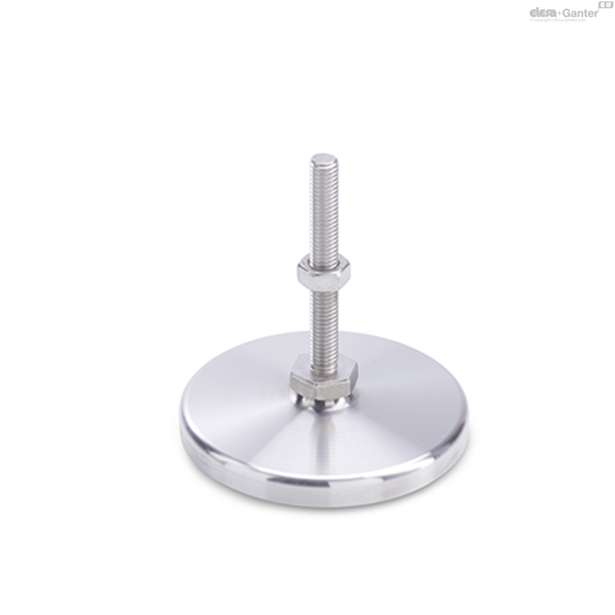
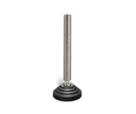
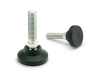
GN 21
Leveling Feet
Stainless Steel, with Turned Base Plate, without Mounting Holes
GN 21-S/SK
Leveling Feet
With / without nut, external hex at the bottom
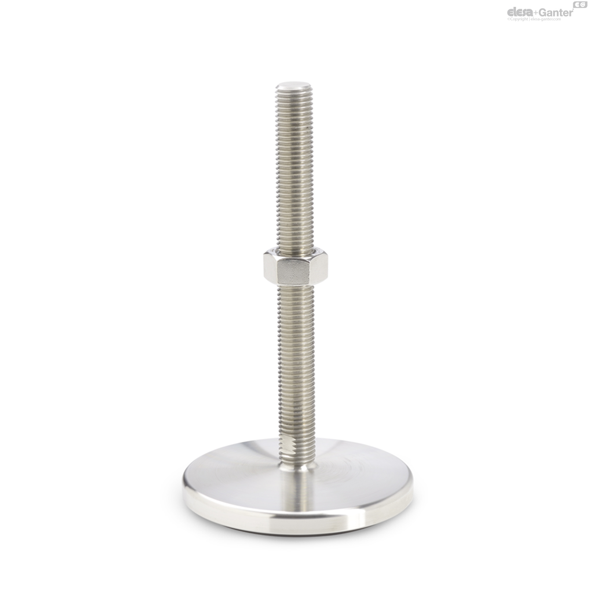
GN 21-T/TK
Leveling Feet
With / without nut, wrench flat at the bottom
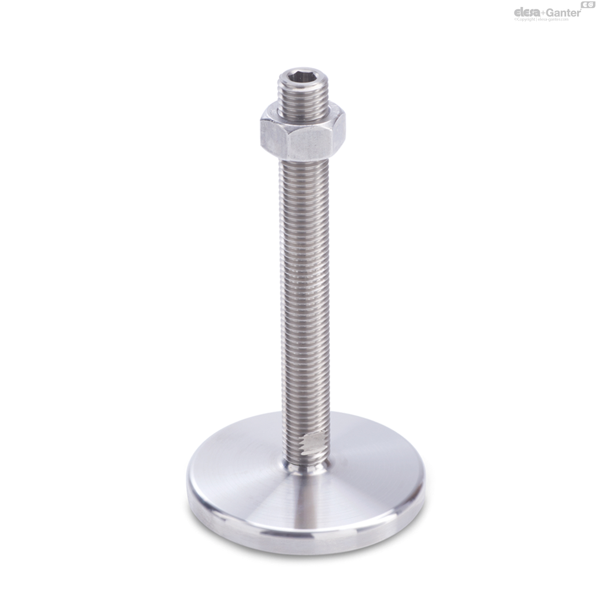
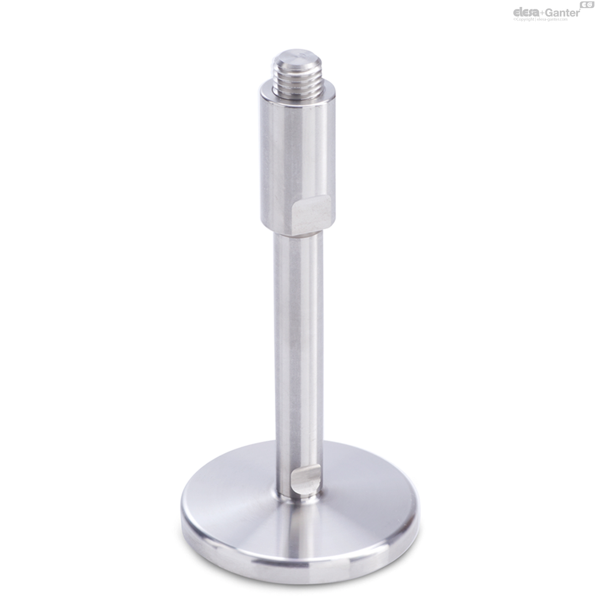
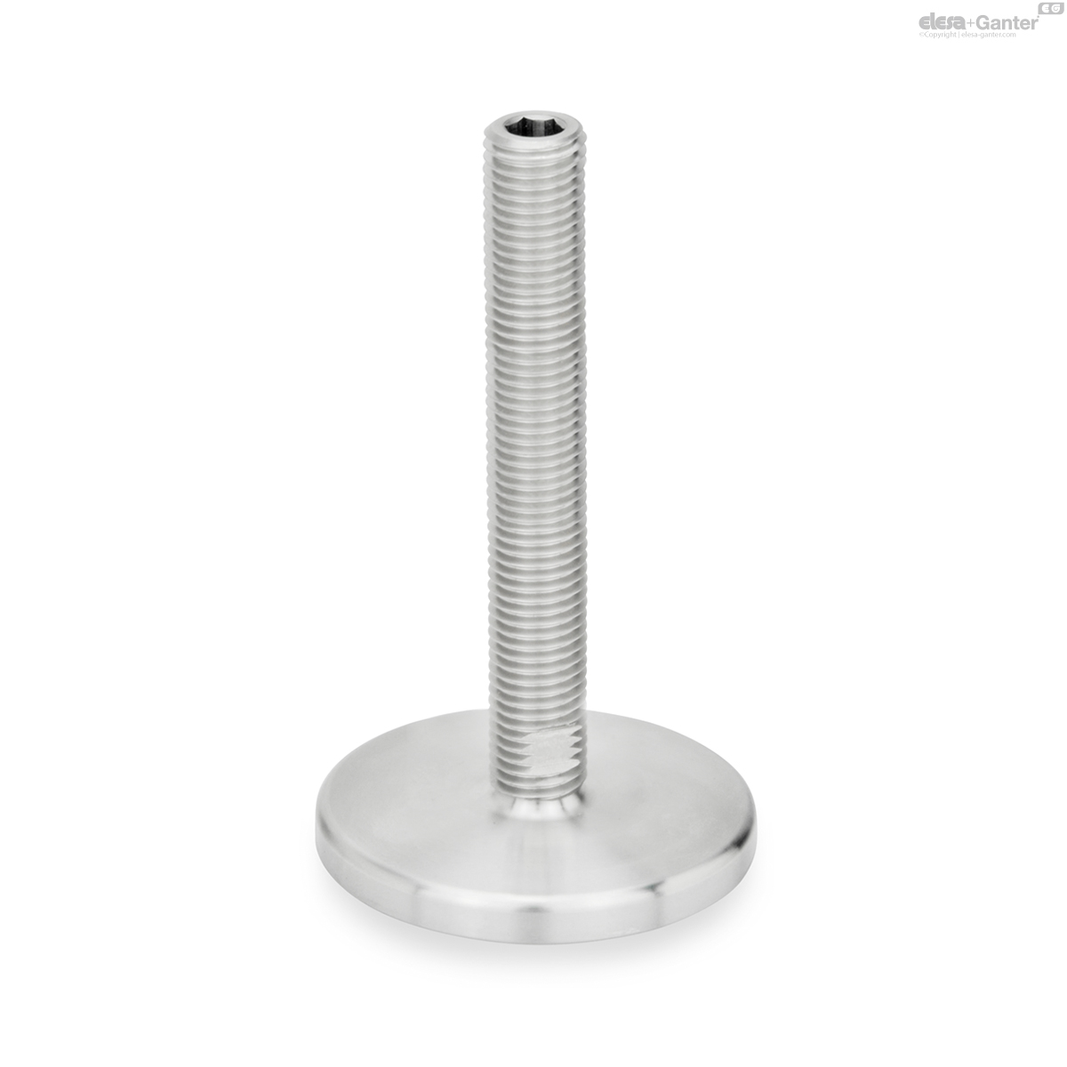
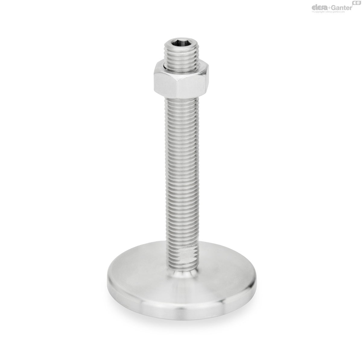
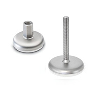
GN 21-U/UK
Leveling Feet
With / without nut, hex socket at the top and wrench flat at the bottom
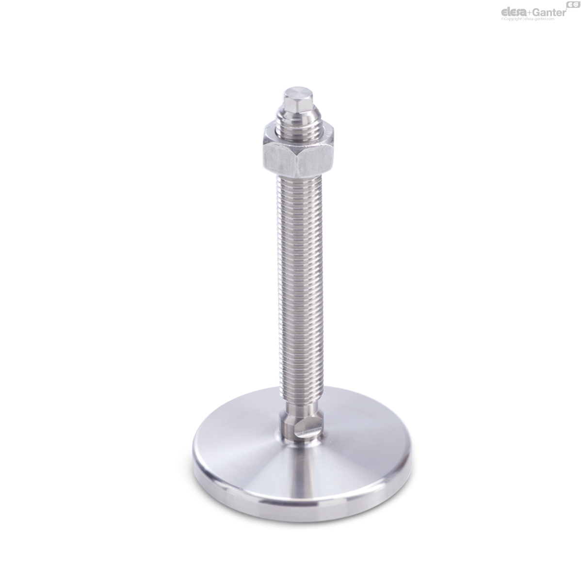
GN 21-V/VK
Leveling Feet
With / without nut, external hex at the top and wrench flat at the bottom
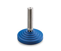
GN 21-W
Leveling Feet
With adjustable sleeve, covered thread and wrench flat at the bottom
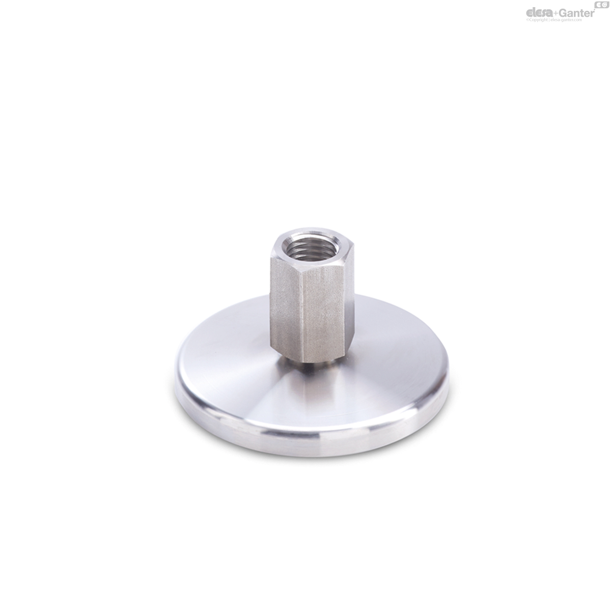
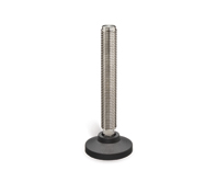
GN 21-X
Leveling Feet
External hex with internal thread
Description
Specification
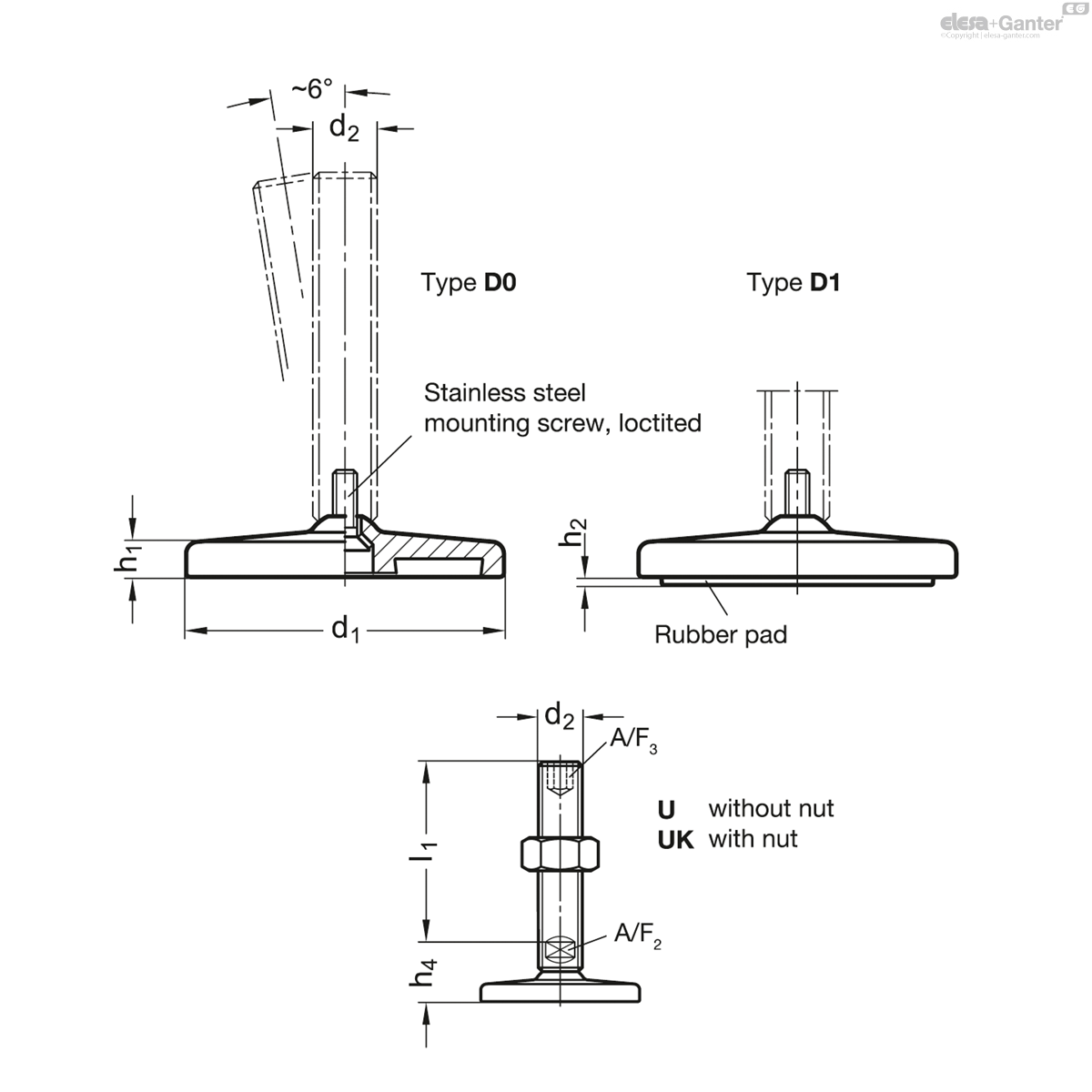
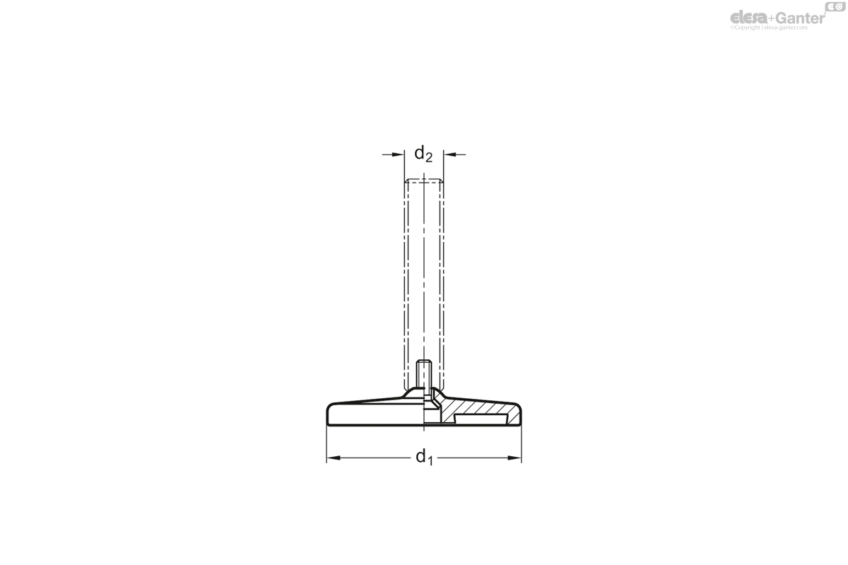
Type (Foot plate)
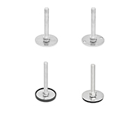
- Type D0: Fine turned, without rubber underlay
- Type D1: Fine turned, with rubber underlay, inlaid, black
Version of the screw
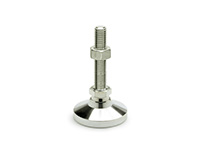
- Version S: Without nut, external hex at the bottom
- Version SK: With nut, external hex at the bottom
- Version T: Without nut, wrench flat at the bottom
- Version TK: With nut, wrench flat at the bottom
- Version U: Without nut, hex socket at the top and wrench flat at the bottom
- Version UK: With nut, hex socket at the top and wrench flat at the bottom
- Version V : Without nut, external hex at the top and wrench flat at the bottom
- Version VK: With nut, external hex at the top and wrench flat at the bottom
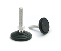
- Version W: With adjustable sleeve, covered thread and wrench flat at the bottom
- Version X: External hex with internal thread
Base plate
Stainless Steel AISI 304
Threaded stem
Stainless Steel AISI 303
Hex nut ISO 4032
Stainless Steel AISI 304
Rubber underlay, inlaid
NBR (Perbunan®), 70 Shore A
Information
Leveling feet GN 21 will be delivered mounted and are not removable.
Technical information
- Plastic Characteristics
- Stainless Steel Characteristics
Load Rating of Leveling Feet
| d1 | d2 | Static load in kN | - | - | - | - |
| - | - | Versions of threaded stem | - | - | - | - |
| - | - | S / SK | T / TK and U / UK | V / VK | W | X |
| 80 | M 8 | 6 | - | - | - | 17 |
| 80 | M 10 | 11 | - | - | - | 17 |
| 80 | M 12 | 16 | - | - | - | 17 |
| 80 | M 16 | - | 17 | 21 | 25 | 17 |
| 80 | M 20 | - | 28 | 35 | 35 | 28 |
| 80 | M 24 | - | 46 | 52 | 52 | - |
| 100 | M 8 | 6 | - | - | - | 17 |
| 100 | M 10 | 11 | - | - | - | 17 |
| 100 | M 12 | 16 | - | - | - | 17 |
| 100 | M 16 | - | 17 | 21 | 25 | 17 |
| 100 | M 20 | - | 28 | 35 | 35 | 28 |
| 100 | M 24 | - | 46 | 52 | 52 | - |
| 120 | M 20 | - | 28 | - | - | 28 |
| 120 | M 24 | - | 46 | - | - | - |
| 120 | M 30 | - | 43 | - | - | - |
At a spindle thread size M 10 and higher, the static load of the leveling feet GN 21 is limited owing to the permissible contact pressure of the adjustment spindle acting on the base plate (at a spindle strength ≥ 500 N/mm2). The values given in the table (valid for type D0 without rubber underlay) assume a clean pressure load perpendicular to the base plate. Bending and buckling stress which often occurs in practice results in a lower load-bearing capacity of the adjustment spindle and may have to be taken into account.
The details given on strength are non-binding guide values without any liability. In general, they do not constitute a warranty or quality.
The user must determine from case to case if a product is suitable for the intended purpose or use. Environmental factors may influence the stated values.
Versions of threaded stem
| Versions of threaded stem | ||
| S / SK: External hex at the bottom at d2 M 8, M 10, M 12 | T / TK: Wrench flat at the bottom at d2 M 16, M 20, M 24, M 30 | U / UK: Hex socket at the top and wrench flat at the bottom at d2 M 16, M 20, M 24, M 30 |
| V / VK: External hex at the top and wrench flat at the bottom at d2 M 16, M 20, M 24 | W: Covered thread and wrench flat at the bottom at d2 M 16, M 20, M 24 | X: External hex with internal thread at d2 M 8, M 10, M 12, M 16, M 20 |
GN 21-U/UK
| Color | d1 | d2 | l1 | h1 | h2 | h4 | A/F 2 | A/F 3 | Static load in kN |
|||
|---|---|---|---|---|---|---|---|---|---|---|---|---|
| Code | Actions | |||||||||||
| GN 21-80-M16-75-D0-U | Type U | 80 | M 16 | 75 | 8.5 | - | 25.5 | 12 | 8 | 17 | 388 |
|
| GN 21-80-M16-75-D0-UK | Type UK | 80 | M 16 | 75 | 8.5 | - | 25.5 | 12 | 8 | 17 | 422 |
|
| GN 21-80-M16-75-D1-U | Type U | 80 | M 16 | 75 | - | 2 | 25.5 | 12 | 8 | 17 | 410 |
|
| GN 21-80-M16-75-D1-UK | Type UK | 80 | M 16 | 75 | - | 2 | 25.5 | 12 | 8 | 17 | 444 |
|
| GN 21-80-M16-100-D0-U | Type U | 80 | M 16 | 100 | 8.5 | - | 25.5 | 12 | 8 | 17 | 420 |
|
| GN 21-80-M16-100-D0-UK | Type UK | 80 | M 16 | 100 | 8.5 | - | 25.5 | 12 | 8 | 17 | 454 |
|
| GN 21-80-M16-100-D1-U | Type U | 80 | M 16 | 100 | - | 2 | 25.5 | 12 | 8 | 17 | 442 |
|
| GN 21-80-M16-100-D1-UK | Type UK | 80 | M 16 | 100 | - | 2 | 25.5 | 12 | 8 | 17 | 476 |
|
| GN 21-80-M16-125-D0-U | Type U | 80 | M 16 | 125 | 8.5 | - | 25.5 | 12 | 8 | 17 | 427 |
|
| GN 21-80-M16-125-D0-UK | Type UK | 80 | M 16 | 125 | 8.5 | - | 25.5 | 12 | 8 | 17 | 461 |
|
| GN 21-80-M16-125-D1-U | Type U | 80 | M 16 | 125 | - | 2 | 25.5 | 12 | 8 | 17 | 449 |
|
| GN 21-80-M16-125-D1-UK | Type UK | 80 | M 16 | 125 | - | 2 | 25.5 | 12 | 8 | 17 | 483 |
|
| GN 21-80-M16-150-D0-U | Type U | 80 | M 16 | 150 | 8.5 | - | 25.5 | 12 | 8 | 17 | 485 |
|
| GN 21-80-M16-150-D0-UK | Type UK | 80 | M 16 | 150 | 8.5 | - | 25.5 | 12 | 8 | 17 | 519 |
|
| GN 21-80-M16-150-D1-U | Type U | 80 | M 16 | 150 | - | 2 | 25.5 | 12 | 8 | 17 | 507 |
|
| GN 21-80-M16-150-D1-UK | Type UK | 80 | M 16 | 150 | - | 2 | 25.5 | 12 | 8 | 17 | 541 |
|
| GN 21-80-M16-200-D0-U | Type U | 80 | M 16 | 200 | 8.5 | - | 25.5 | 12 | 8 | 17 | 551 |
|
| GN 21-80-M16-200-D0-UK | Type UK | 80 | M 16 | 200 | 8.5 | - | 25.5 | 12 | 8 | 17 | 579 |
|
| GN 21-80-M16-200-D1-U | Type U | 80 | M 16 | 200 | - | 2 | 25.5 | 12 | 8 | 17 | 573 |
|
| GN 21-80-M16-200-D1-UK | Type UK | 80 | M 16 | 200 | - | 2 | 25.5 | 12 | 8 | 17 | 601 |
|
| GN 21-80-M16-250-D0-U | Type U | 80 | M 16 | 250 | 8.5 | - | 25.5 | 12 | 8 | 17 | 616 |
|
| GN 21-80-M16-250-D0-UK | Type UK | 80 | M 16 | 250 | 8.5 | - | 25.5 | 12 | 8 | 17 | 644 |
|
| GN 21-80-M16-250-D1-U | Type U | 80 | M 16 | 250 | - | 2 | 25.5 | 12 | 8 | 17 | 638 |
|
| GN 21-80-M16-250-D1-UK | Type UK | 80 | M 16 | 250 | - | 2 | 25.5 | 12 | 8 | 17 | 667 |
|
| GN 21-80-M20-75-D0-U | Type U | 80 | M 20 | 75 | 8.5 | - | 27 | 15 | 10 | 28 | 455 |
|
| GN 21-80-M20-75-D0-UK | Type UK | 80 | M 20 | 75 | 8.5 | - | 27 | 15 | 10 | 28 | 508 |
|
| GN 21-80-M20-75-D1-U | Type U | 80 | M 20 | 75 | - | 2 | 27 | 15 | 10 | 28 | 477 |
|
| GN 21-80-M20-75-D1-UK | Type UK | 80 | M 20 | 75 | - | 2 | 27 | 15 | 10 | 28 | 530 |
|
| GN 21-80-M20-100-D0-U | Type U | 80 | M 20 | 100 | 8.5 | - | 27 | 15 | 10 | 28 | 693 |
|
| GN 21-80-M20-100-D0-UK | Type UK | 80 | M 20 | 100 | 8.5 | - | 27 | 15 | 10 | 28 | 746 |
|
| GN 21-80-M20-100-D1-U | Type U | 80 | M 20 | 100 | - | 2 | 27 | 15 | 10 | 28 | 715 |
|
| GN 21-80-M20-100-D1-UK | Type UK | 80 | M 20 | 100 | - | 2 | 27 | 15 | 10 | 28 | 768 |
|
| GN 21-80-M20-125-D0-U | Type U | 80 | M 20 | 125 | 8.5 | - | 27 | 15 | 10 | 28 | 556 |
|
| GN 21-80-M20-125-D0-UK | Type UK | 80 | M 20 | 125 | 8.5 | - | 27 | 15 | 10 | 28 | 609 |
|
| GN 21-80-M20-125-D1-U | Type U | 80 | M 20 | 125 | - | 2 | 27 | 15 | 10 | 28 | 578 |
|
| GN 21-80-M20-125-D1-UK | Type UK | 80 | M 20 | 125 | - | 2 | 27 | 15 | 10 | 28 | 631 |
|
| GN 21-80-M20-150-D0-U | Type U | 80 | M 20 | 150 | 8.5 | - | 27 | 15 | 10 | 28 | 614 |
|
| GN 21-80-M20-150-D0-UK | Type UK | 80 | M 20 | 150 | 8.5 | - | 27 | 15 | 10 | 28 | 667 |
|
| GN 21-80-M20-150-D1-U | Type U | 80 | M 20 | 150 | - | 2 | 27 | 15 | 10 | 28 | 636 |
|
| GN 21-80-M20-150-D1-UK | Type UK | 80 | M 20 | 150 | - | 2 | 27 | 15 | 10 | 28 | 689 |
|
| GN 21-80-M20-200-D0-U | Type U | 80 | M 20 | 200 | 8.5 | - | 27 | 15 | 10 | 28 | 709 |
|
| GN 21-80-M20-200-D0-UK | Type UK | 80 | M 20 | 200 | 8.5 | - | 27 | 15 | 10 | 28 | 762 |
|
| GN 21-80-M20-200-D1-U | Type U | 80 | M 20 | 200 | - | 2 | 27 | 15 | 10 | 28 | 731 |
|
| GN 21-80-M20-200-D1-UK | Type UK | 80 | M 20 | 200 | - | 2 | 27 | 15 | 10 | 28 | 784 |
|
| GN 21-80-M20-250-D0-U | Type U | 80 | M 20 | 250 | 8.5 | - | 27 | 15 | 10 | 28 | 1232 |
|
| GN 21-80-M20-250-D0-UK | Type UK | 80 | M 20 | 250 | 8.5 | - | 27 | 15 | 10 | 28 | 1285 |
|
| GN 21-80-M20-250-D1-U | Type U | 80 | M 20 | 250 | - | 2 | 27 | 15 | 10 | 28 | 1254 |
|
| GN 21-80-M20-250-D1-UK | Type UK | 80 | M 20 | 250 | - | 2 | 27 | 15 | 10 | 28 | 1307 |
|
| GN 21-80-M24-100-D0-U | Type U | 80 | M 24 | 100 | 8.5 | - | 30.5 | 19 | 12 | 46 | 693 |
|
| GN 21-80-M24-100-D0-UK | Type UK | 80 | M 24 | 100 | 8.5 | - | 30.5 | 19 | 12 | 46 | 793 |
|
| GN 21-80-M24-100-D1-U | Type U | 80 | M 24 | 100 | - | 2 | 30.5 | 19 | 12 | 46 | 715 |
|
| GN 21-80-M24-100-D1-UK | Type UK | 80 | M 24 | 100 | - | 2 | 30.5 | 19 | 12 | 46 | 815 |
|
| GN 21-80-M24-125-D0-U | Type U | 80 | M 24 | 125 | 8.5 | - | 30.5 | 19 | 12 | 46 | 685 |
|
| GN 21-80-M24-125-D0-UK | Type UK | 80 | M 24 | 125 | 8.5 | - | 30.5 | 19 | 12 | 46 | 785 |
|
| GN 21-80-M24-125-D1-U | Type U | 80 | M 24 | 125 | - | 2 | 30.5 | 19 | 12 | 46 | 707 |
|
| GN 21-80-M24-125-D1-UK | Type UK | 80 | M 24 | 125 | - | 2 | 30.5 | 19 | 12 | 46 | 807 |
|
| GN 21-80-M24-150-D0-U | Type U | 80 | M 24 | 150 | 8.5 | - | 30.5 | 19 | 12 | 46 | 766 |
|
| GN 21-80-M24-150-D0-UK | Type UK | 80 | M 24 | 150 | 8.5 | - | 30.5 | 19 | 12 | 46 | 866 |
|
| GN 21-80-M24-150-D1-U | Type U | 80 | M 24 | 150 | - | 2 | 30.5 | 19 | 12 | 46 | 788 |
|
| GN 21-80-M24-150-D1-UK | Type UK | 80 | M 24 | 150 | - | 2 | 30.5 | 19 | 12 | 46 | 888 |
|
| GN 21-80-M24-200-D0-U | Type U | 80 | M 24 | 200 | 8.5 | - | 30.5 | 19 | 12 | 46 | 902 |
|
| GN 21-80-M24-200-D0-UK | Type UK | 80 | M 24 | 200 | 8.5 | - | 30.5 | 19 | 12 | 46 | 1002 |
|
| GN 21-80-M24-200-D1-U | Type U | 80 | M 24 | 200 | - | 2 | 30.5 | 19 | 12 | 46 | 924 |
|
| GN 21-80-M24-200-D1-UK | Type UK | 80 | M 24 | 200 | - | 2 | 30.5 | 19 | 12 | 46 | 1024 |
|
| GN 21-80-M24-300-D0-U | Type U | 80 | M 24 | 300 | 8.5 | - | 30.5 | 19 | 12 | 46 | 1711 |
|
| GN 21-80-M24-300-D0-UK | Type UK | 80 | M 24 | 300 | 8.5 | - | 30.5 | 19 | 12 | 46 | 1811 |
|
| GN 21-80-M24-300-D1-U | Type U | 80 | M 24 | 300 | - | 2 | 30.5 | 19 | 12 | 46 | 1733 |
|
| GN 21-80-M24-300-D1-UK | Type UK | 80 | M 24 | 300 | - | 2 | 30.5 | 19 | 12 | 46 | 1833 |
|
| GN 21-100-M16-75-D0-U | Type U | 100 | M 16 | 75 | 9 | - | 26.5 | 12 | 8 | 17 | 577 |
|
| GN 21-100-M16-75-D0-UK | Type UK | 100 | M 16 | 75 | 9 | - | 26.5 | 12 | 8 | 17 | 611 |
|
| GN 21-100-M16-75-D1-U | Type U | 100 | M 16 | 75 | - | 3 | 26.5 | 12 | 8 | 17 | 620 |
|
| GN 21-100-M16-75-D1-UK | Type UK | 100 | M 16 | 75 | - | 3 | 26.5 | 12 | 8 | 17 | 654 |
|
| GN 21-100-M16-100-D0-U | Type U | 100 | M 16 | 100 | 9 | - | 26.5 | 12 | 8 | 17 | 609 |
|
| GN 21-100-M16-100-D0-UK | Type UK | 100 | M 16 | 100 | 9 | - | 26.5 | 12 | 8 | 17 | 643 |
|
| GN 21-100-M16-100-D1-U | Type U | 100 | M 16 | 100 | - | 3 | 26.5 | 12 | 8 | 17 | 652 |
|
| GN 21-100-M16-100-D1-UK | Type UK | 100 | M 16 | 100 | - | 3 | 26.5 | 12 | 8 | 17 | 686 |
|
| GN 21-100-M16-125-D0-U | Type U | 100 | M 16 | 125 | 9 | - | 26.5 | 12 | 8 | 17 | 616 |
|
| GN 21-100-M16-125-D0-UK | Type UK | 100 | M 16 | 125 | 9 | - | 26.5 | 12 | 8 | 17 | 650 |
|
| GN 21-100-M16-125-D1-U | Type U | 100 | M 16 | 125 | - | 3 | 26.5 | 12 | 8 | 17 | 659 |
|
| GN 21-100-M16-125-D1-UK | Type UK | 100 | M 16 | 125 | - | 3 | 26.5 | 12 | 8 | 17 | 693 |
|
| GN 21-100-M16-150-D0-U | Type U | 100 | M 16 | 150 | 9 | - | 26.5 | 12 | 8 | 17 | 674 |
|
| GN 21-100-M16-150-D0-UK | Type UK | 100 | M 16 | 150 | 9 | - | 26.5 | 12 | 8 | 17 | 708 |
|
| GN 21-100-M16-150-D1-U | Type U | 100 | M 16 | 150 | - | 3 | 26.5 | 12 | 8 | 17 | 717 |
|
| GN 21-100-M16-150-D1-UK | Type UK | 100 | M 16 | 150 | - | 3 | 26.5 | 12 | 8 | 17 | 751 |
|
| GN 21-100-M16-200-D0-U | Type U | 100 | M 16 | 200 | 9 | - | 26.5 | 12 | 8 | 17 | 736 |
|
| GN 21-100-M16-200-D0-UK | Type UK | 100 | M 16 | 200 | 9 | - | 26.5 | 12 | 8 | 17 | 764 |
|
| GN 21-100-M16-200-D1-U | Type U | 100 | M 16 | 200 | - | 3 | 26.5 | 12 | 8 | 17 | 779 |
|
| GN 21-100-M16-200-D1-UK | Type UK | 100 | M 16 | 200 | - | 3 | 26.5 | 12 | 8 | 17 | 807 |
|
| GN 21-100-M16-250-D0-U | Type U | 100 | M 16 | 250 | 9 | - | 26.5 | 12 | 8 | 17 | 1065 |
|
| GN 21-100-M16-250-D0-UK | Type UK | 100 | M 16 | 250 | 9 | - | 26.5 | 12 | 8 | 17 | 1093 |
|
| GN 21-100-M16-250-D1-U | Type U | 100 | M 16 | 250 | - | 3 | 26.5 | 12 | 8 | 17 | 1108 |
|
| GN 21-100-M16-250-D1-UK | Type UK | 100 | M 16 | 250 | - | 3 | 26.5 | 12 | 8 | 17 | 1136 |
|
| GN 21-100-M20-75-D0-U | Type U | 100 | M 20 | 75 | 9 | - | 28 | 15 | 10 | 28 | 636 |
|
| GN 21-100-M20-75-D0-UK | Type UK | 100 | M 20 | 75 | 9 | - | 28 | 15 | 10 | 28 | 689 |
|
| GN 21-100-M20-75-D1-U | Type U | 100 | M 20 | 75 | - | 3 | 28 | 15 | 10 | 28 | 679 |
|
| GN 21-100-M20-75-D1-UK | Type UK | 100 | M 20 | 75 | - | 3 | 28 | 15 | 10 | 28 | 732 |
|
| GN 21-100-M20-100-D0-U | Type U | 100 | M 20 | 100 | 9 | - | 28 | 15 | 10 | 28 | 874 |
|
| GN 21-100-M20-100-D0-UK | Type UK | 100 | M 20 | 100 | 9 | - | 28 | 15 | 10 | 28 | 927 |
|
| GN 21-100-M20-100-D1-U | Type U | 100 | M 20 | 100 | - | 3 | 28 | 15 | 10 | 28 | 917 |
|
| GN 21-100-M20-100-D1-UK | Type UK | 100 | M 20 | 100 | - | 3 | 28 | 15 | 10 | 28 | 970 |
|
| GN 21-100-M20-125-D0-U | Type U | 100 | M 20 | 125 | 9 | - | 28 | 15 | 10 | 28 | 737 |
|
| GN 21-100-M20-125-D0-UK | Type UK | 100 | M 20 | 125 | 9 | - | 28 | 15 | 10 | 28 | 790 |
|
| GN 21-100-M20-125-D1-U | Type U | 100 | M 20 | 125 | - | 3 | 28 | 15 | 10 | 28 | 780 |
|
| GN 21-100-M20-125-D1-UK | Type UK | 100 | M 20 | 125 | - | 3 | 28 | 15 | 10 | 28 | 833 |
|
| GN 21-100-M20-150-D0-U | Type U | 100 | M 20 | 150 | 9 | - | 28 | 15 | 10 | 28 | 795 |
|
| GN 21-100-M20-150-D0-UK | Type UK | 100 | M 20 | 150 | 9 | - | 28 | 15 | 10 | 28 | 848 |
|
| GN 21-100-M20-150-D1-U | Type U | 100 | M 20 | 150 | - | 3 | 28 | 15 | 10 | 28 | 838 |
|
| GN 21-100-M20-150-D1-UK | Type UK | 100 | M 20 | 150 | - | 3 | 28 | 15 | 10 | 28 | 891 |
|
| GN 21-100-M20-200-D0-U | Type U | 100 | M 20 | 200 | 9 | - | 28 | 15 | 10 | 28 | 890 |
|
| GN 21-100-M20-200-D0-UK | Type UK | 100 | M 20 | 200 | 9 | - | 28 | 15 | 10 | 28 | 943 |
|
| GN 21-100-M20-200-D1-U | Type U | 100 | M 20 | 200 | - | 3 | 28 | 15 | 10 | 28 | 933 |
|
| GN 21-100-M20-200-D1-UK | Type UK | 100 | M 20 | 200 | - | 3 | 28 | 15 | 10 | 28 | 986 |
|
| GN 21-100-M20-250-D0-U | Type U | 100 | M 20 | 250 | 9 | - | 28 | 15 | 10 | 28 | 1413 |
|
| GN 21-100-M20-250-D0-UK | Type UK | 100 | M 20 | 250 | 9 | - | 28 | 15 | 10 | 28 | 1466 |
|
| GN 21-100-M20-250-D1-U | Type U | 100 | M 20 | 250 | - | 3 | 28 | 15 | 10 | 28 | 1456 |
|
| GN 21-100-M20-250-D1-UK | Type UK | 100 | M 20 | 250 | - | 3 | 28 | 15 | 10 | 28 | 1509 |
|
| GN 21-100-M24-100-D0-U | Type U | 100 | M 24 | 100 | 9 | - | 31.5 | 19 | 12 | 46 | 878 |
|
| GN 21-100-M24-100-D0-UK | Type UK | 100 | M 24 | 100 | 9 | - | 31.5 | 19 | 12 | 46 | 978 |
|
| GN 21-100-M24-100-D1-U | Type U | 100 | M 24 | 100 | - | 3 | 31.5 | 19 | 12 | 46 | 921 |
|
| GN 21-100-M24-100-D1-UK | Type UK | 100 | M 24 | 100 | - | 3 | 31.5 | 19 | 12 | 46 | 1021 |
|
| GN 21-100-M24-125-D0-U | Type U | 100 | M 24 | 125 | 9 | - | 31.5 | 19 | 12 | 46 | 870 |
|
| GN 21-100-M24-125-D0-UK | Type UK | 100 | M 24 | 125 | 9 | - | 31.5 | 19 | 12 | 46 | 970 |
|
| GN 21-100-M24-125-D1-U | Type U | 100 | M 24 | 125 | - | 3 | 31.5 | 19 | 12 | 46 | 913 |
|
| GN 21-100-M24-125-D1-UK | Type UK | 100 | M 24 | 125 | - | 3 | 31.5 | 19 | 12 | 46 | 1013 |
|
| GN 21-100-M24-150-D0-U | Type U | 100 | M 24 | 150 | 9 | - | 31.5 | 19 | 12 | 46 | 951 |
|
| GN 21-100-M24-150-D0-UK | Type UK | 100 | M 24 | 150 | 9 | - | 31.5 | 19 | 12 | 46 | 1051 |
|
| GN 21-100-M24-150-D1-U | Type U | 100 | M 24 | 150 | - | 3 | 31.5 | 19 | 12 | 46 | 994 |
|
| GN 21-100-M24-150-D1-UK | Type UK | 100 | M 24 | 150 | - | 3 | 31.5 | 19 | 12 | 46 | 1094 |
|
| GN 21-100-M24-200-D0-U | Type U | 100 | M 24 | 200 | 9 | - | 31.5 | 19 | 12 | 46 | 1087 |
|
| GN 21-100-M24-200-D0-UK | Type UK | 100 | M 24 | 200 | 9 | - | 31.5 | 19 | 12 | 46 | 1187 |
|
| GN 21-100-M24-200-D1-U | Type U | 100 | M 24 | 200 | - | 3 | 31.5 | 19 | 12 | 46 | 1130 |
|
| GN 21-100-M24-200-D1-UK | Type UK | 100 | M 24 | 200 | - | 3 | 31.5 | 19 | 12 | 46 | 1230 |
|
| GN 21-100-M24-300-D0-U | Type U | 100 | M 24 | 300 | 9 | - | 31.5 | 19 | 12 | 46 | 1896 |
|
| GN 21-100-M24-300-D0-UK | Type UK | 100 | M 24 | 300 | 9 | - | 31.5 | 19 | 12 | 46 | 1996 |
|
| GN 21-100-M24-300-D1-U | Type U | 100 | M 24 | 300 | - | 3 | 31.5 | 19 | 12 | 46 | 1939 |
|
| GN 21-100-M24-300-D1-UK | Type UK | 100 | M 24 | 300 | - | 3 | 31.5 | 19 | 12 | 46 | 2039 |
|
| GN 21-120-M20-75-D0-U | Type U | 120 | M 20 | 75 | 12 | - | 32 | 15 | 10 | 28 | 989 |
|
| GN 21-120-M20-75-D0-UK | Type UK | 120 | M 20 | 75 | 12 | - | 32 | 15 | 10 | 28 | 1042 |
|
| GN 21-120-M20-75-D1-U | Type U | 120 | M 20 | 75 | - | 3.5 | 32 | 15 | 10 | 28 | 1071 |
|
| GN 21-120-M20-75-D1-UK | Type UK | 120 | M 20 | 75 | - | 3.5 | 32 | 15 | 10 | 28 | 1124 |
|
| GN 21-120-M20-100-D0-U | Type U | 120 | M 20 | 100 | 12 | - | 32 | 15 | 10 | 28 | 1227 |
|
| GN 21-120-M20-100-D0-UK | Type UK | 120 | M 20 | 100 | 12 | - | 32 | 15 | 10 | 28 | 1280 |
|
| GN 21-120-M20-100-D1-U | Type U | 120 | M 20 | 100 | - | 3.5 | 32 | 15 | 10 | 28 | 1309 |
|
| GN 21-120-M20-100-D1-UK | Type UK | 120 | M 20 | 100 | - | 3.5 | 32 | 15 | 10 | 28 | 1362 |
|
| GN 21-120-M20-125-D0-U | Type U | 120 | M 20 | 125 | 12 | - | 32 | 15 | 10 | 28 | 1090 |
|
| GN 21-120-M20-125-D0-UK | Type UK | 120 | M 20 | 125 | 12 | - | 32 | 15 | 10 | 28 | 1143 |
|
| GN 21-120-M20-125-D1-U | Type U | 120 | M 20 | 125 | - | 3.5 | 32 | 15 | 10 | 28 | 1172 |
|
| GN 21-120-M20-125-D1-UK | Type UK | 120 | M 20 | 125 | - | 3.5 | 32 | 15 | 10 | 28 | 1225 |
|
| GN 21-120-M20-150-D0-U | Type U | 120 | M 20 | 150 | 12 | - | 32 | 15 | 10 | 28 | 1148 |
|
| GN 21-120-M20-150-D0-UK | Type UK | 120 | M 20 | 150 | 12 | - | 32 | 15 | 10 | 28 | 1201 |
|
| GN 21-120-M20-150-D1-U | Type U | 120 | M 20 | 150 | - | 3.5 | 32 | 15 | 10 | 28 | 1230 |
|
| GN 21-120-M20-150-D1-UK | Type UK | 120 | M 20 | 150 | - | 3.5 | 32 | 15 | 10 | 28 | 1283 |
|
| GN 21-120-M20-200-D0-U | Type U | 120 | M 20 | 200 | 12 | - | 32 | 15 | 10 | 28 | 1243 |
|
| GN 21-120-M20-200-D0-UK | Type UK | 120 | M 20 | 200 | 12 | - | 32 | 15 | 10 | 28 | 1296 |
|
| GN 21-120-M20-200-D1-U | Type U | 120 | M 20 | 200 | - | 3.5 | 32 | 15 | 10 | 28 | 1325 |
|
| GN 21-120-M20-200-D1-UK | Type UK | 120 | M 20 | 200 | - | 3.5 | 32 | 15 | 10 | 28 | 1378 |
|
| GN 21-120-M20-250-D0-U | Type U | 120 | M 20 | 250 | 12 | - | 32 | 15 | 10 | 28 | 1766 |
|
| GN 21-120-M20-250-D0-UK | Type UK | 120 | M 20 | 250 | 12 | - | 32 | 15 | 10 | 28 | 1819 |
|
| GN 21-120-M20-250-D1-U | Type U | 120 | M 20 | 250 | - | 3.5 | 32 | 15 | 10 | 28 | 1848 |
|
| GN 21-120-M20-250-D1-UK | Type UK | 120 | M 20 | 250 | - | 3.5 | 32 | 15 | 10 | 28 | 1901 |
|
| GN 21-120-M24-100-D0-U | Type U | 120 | M 24 | 100 | 12 | - | 35.5 | 19 | 12 | 46 | 1228 |
|
| GN 21-120-M24-100-D0-UK | Type UK | 120 | M 24 | 100 | 12 | - | 35.5 | 19 | 12 | 46 | 1328 |
|
| GN 21-120-M24-100-D1-U | Type U | 120 | M 24 | 100 | - | 3.5 | 35.5 | 19 | 12 | 46 | 1310 |
|
| GN 21-120-M24-100-D1-UK | Type UK | 120 | M 24 | 100 | - | 3.5 | 35.5 | 19 | 12 | 46 | 1410 |
|
| GN 21-120-M24-125-D0-U | Type U | 120 | M 24 | 125 | 12 | - | 35.5 | 19 | 12 | 46 | 1220 |
|
| GN 21-120-M24-125-D0-UK | Type UK | 120 | M 24 | 125 | 12 | - | 35.5 | 19 | 12 | 46 | 1320 |
|
| GN 21-120-M24-125-D1-U | Type U | 120 | M 24 | 125 | - | 3.5 | 35.5 | 19 | 12 | 46 | 1302 |
|
| GN 21-120-M24-125-D1-UK | Type UK | 120 | M 24 | 125 | - | 3.5 | 35.5 | 19 | 12 | 46 | 1402 |
|
| GN 21-120-M24-150-D0-U | Type U | 120 | M 24 | 150 | 12 | - | 35.5 | 19 | 12 | 46 | 1301 |
|
| GN 21-120-M24-150-D0-UK | Type UK | 120 | M 24 | 150 | 12 | - | 35.5 | 19 | 12 | 46 | 1401 |
|
| GN 21-120-M24-150-D1-U | Type U | 120 | M 24 | 150 | - | 3.5 | 35.5 | 19 | 12 | 46 | 1383 |
|
| GN 21-120-M24-150-D1-UK | Type UK | 120 | M 24 | 150 | - | 3.5 | 35.5 | 19 | 12 | 46 | 1483 |
|
| GN 21-120-M24-200-D0-U | Type U | 120 | M 24 | 200 | 12 | - | 35.5 | 19 | 12 | 46 | 1437 |
|
| GN 21-120-M24-200-D0-UK | Type UK | 120 | M 24 | 200 | 12 | - | 35.5 | 19 | 12 | 46 | 1537 |
|
| GN 21-120-M24-200-D1-U | Type U | 120 | M 24 | 200 | - | 3.5 | 35.5 | 19 | 12 | 46 | 1519 |
|
| GN 21-120-M24-200-D1-UK | Type UK | 120 | M 24 | 200 | - | 3.5 | 35.5 | 19 | 12 | 46 | 1619 |
|
| GN 21-120-M24-300-D0-U | Type U | 120 | M 24 | 300 | 12 | - | 35.5 | 19 | 12 | 46 | 2246 |
|
| GN 21-120-M24-300-D0-UK | Type UK | 120 | M 24 | 300 | 12 | - | 35.5 | 19 | 12 | 46 | 2346 |
|
| GN 21-120-M24-300-D1-U | Type U | 120 | M 24 | 300 | - | 3.5 | 35.5 | 19 | 12 | 46 | 2328 |
|
| GN 21-120-M24-300-D1-UK | Type UK | 120 | M 24 | 300 | - | 3.5 | 35.5 | 19 | 12 | 46 | 2428 |
|
| GN 21-120-M30-100-D0-U | Type U | 120 | M 30 | 100 | 12 | - | 39.5 | 24 | 12 | 43 | 1353 |
|
| GN 21-120-M30-100-D0-UK | Type UK | 120 | M 30 | 100 | 12 | - | 39.5 | 24 | 12 | 43 | 1552 |
|
| GN 21-120-M30-100-D1-U | Type U | 120 | M 30 | 100 | - | 3.5 | 39.5 | 24 | 12 | 43 | 1436 |
|
| GN 21-120-M30-100-D1-UK | Type UK | 120 | M 30 | 100 | - | 3.5 | 39.5 | 24 | 12 | 43 | 1635 |
|
| GN 21-120-M30-125-D0-U | Type U | 120 | M 30 | 125 | 12 | - | 39.5 | 24 | 12 | 43 | 1469 |
|
| GN 21-120-M30-125-D0-UK | Type UK | 120 | M 30 | 125 | 12 | - | 39.5 | 24 | 12 | 43 | 1668 |
|
| GN 21-120-M30-125-D1-U | Type U | 120 | M 30 | 125 | - | 3.5 | 39.5 | 24 | 12 | 43 | 1552 |
|
| GN 21-120-M30-125-D1-UK | Type UK | 120 | M 30 | 125 | - | 3.5 | 39.5 | 24 | 12 | 43 | 1751 |
|
| GN 21-120-M30-150-D0-U | Type U | 120 | M 30 | 150 | 12 | - | 39.5 | 24 | 12 | 43 | 1581 |
|
| GN 21-120-M30-150-D0-UK | Type UK | 120 | M 30 | 150 | 12 | - | 39.5 | 24 | 12 | 43 | 1780 |
|
| GN 21-120-M30-150-D1-U | Type U | 120 | M 30 | 150 | - | 3.5 | 39.5 | 24 | 12 | 43 | 1664 |
|
| GN 21-120-M30-150-D1-UK | Type UK | 120 | M 30 | 150 | - | 3.5 | 39.5 | 24 | 12 | 43 | 1863 |
|
| GN 21-120-M30-200-D0-U | Type U | 120 | M 30 | 200 | 12 | - | 39.5 | 24 | 12 | 43 | 1811 |
|
| GN 21-120-M30-200-D0-UK | Type UK | 120 | M 30 | 200 | 12 | - | 39.5 | 24 | 12 | 43 | 2010 |
|
| GN 21-120-M30-200-D1-U | Type U | 120 | M 30 | 200 | - | 3.5 | 39.5 | 24 | 12 | 43 | 1894 |
|
| GN 21-120-M30-200-D1-UK | Type UK | 120 | M 30 | 200 | - | 3.5 | 39.5 | 24 | 12 | 43 | 2093 |
|
| GN 21-120-M30-300-D0-U | Type U | 120 | M 30 | 300 | 12 | - | 39.5 | 24 | 12 | 43 | 3225 |
|
| GN 21-120-M30-300-D0-UK | Type UK | 120 | M 30 | 300 | 12 | - | 39.5 | 24 | 12 | 43 | 3424 |
|
| GN 21-120-M30-300-D1-U | Type U | 120 | M 30 | 300 | - | 3.5 | 39.5 | 24 | 12 | 43 | 3308 |
|
| GN 21-120-M30-300-D1-UK | Type UK | 120 | M 30 | 300 | - | 3.5 | 39.5 | 24 | 12 | 43 | 3507 |
|

Enquiry Now
To allow us to respond to your enquiry promptly, please provide all required information.
Related Products
-
 LV.A-STPLevelling feetTechnopolymer base, SUPER-technopolymer stemView Product
 -
 GN 23Leveling FeetStainless Steel, with Turned Base Plate, with Mounting HolesView Product
 -
 LVQ.A-SSTLevelling elementsTechnopolymer base, stainless steel stemView Product
 -
 LV.A-SSTLevelling feetTechnopolymer base, stainless steel stemView Product
 -
 GN 343.6Stainless Steel-Levelling feetAdjustable spindleView Product
 -
 GN 41Leveling FeetStainless SteelView Product
 -
 LS.A-SSTLevelling feetTechnopolymer base, stainless steel stemView Product
 -
 GN 31Leveling FeetStainless Steel, with Rubber PadView Product
 -
 LV.A-SST-VDAdjustable feetVisually Detectable technopolymer base, stainless steel stemView Product
 -
 LSQ.A-SSTLevelling feetTechnopolymer base, stainless steel stemView Product

