

GN 115-WSK-SST
Latches
Stainless Steel, Operation with Socket Keys


Description
Specification
Version in Stainless Steel (NI)
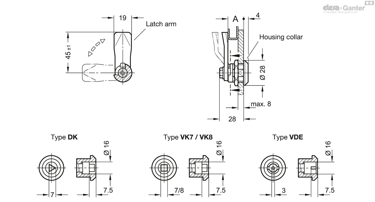
Types
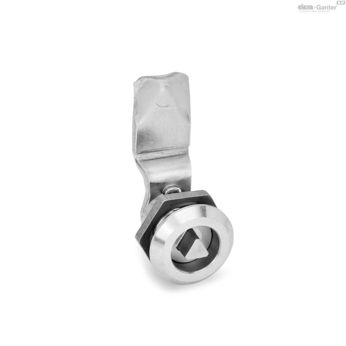
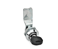
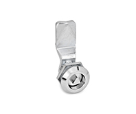
- Type DK: With triangular spindle
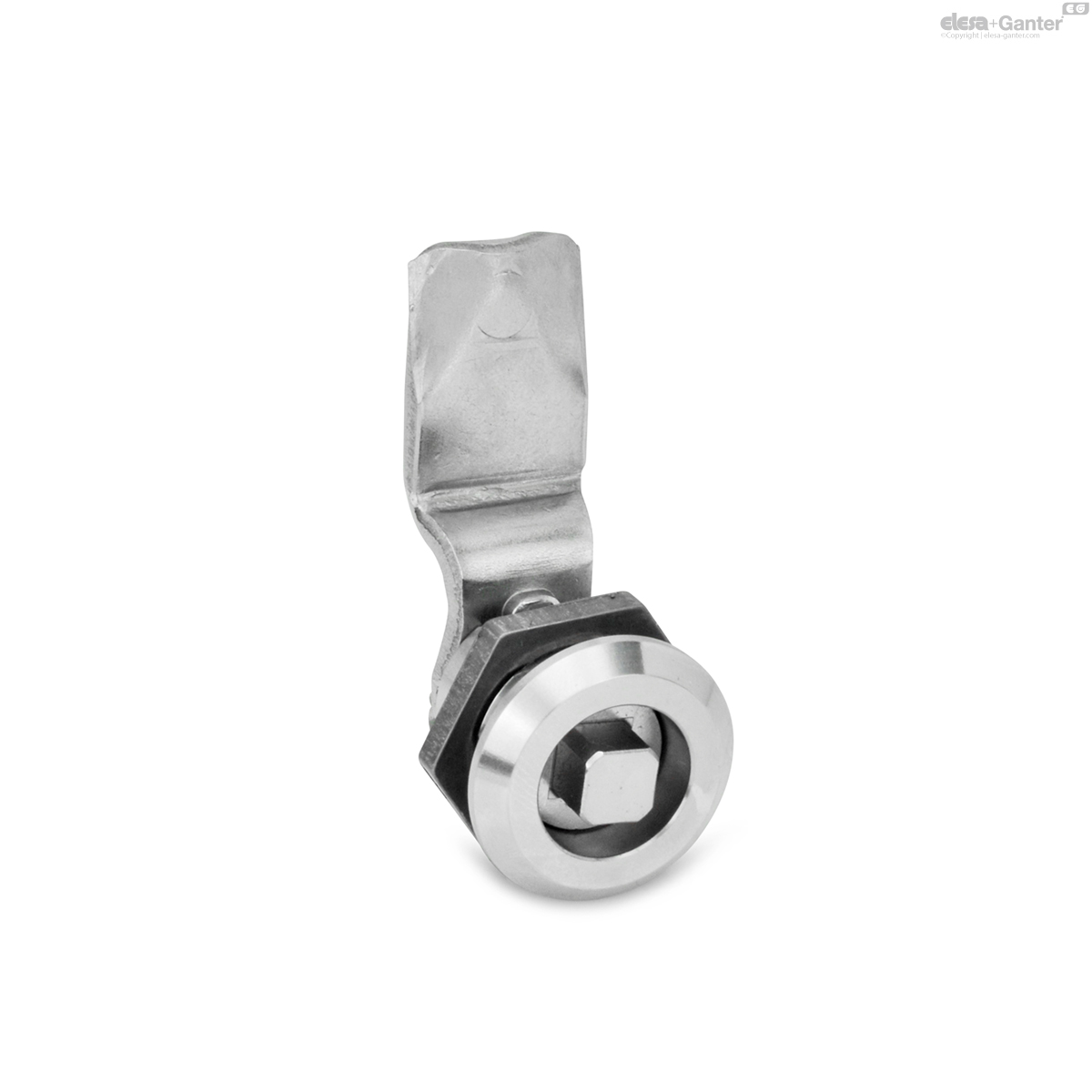
- Type VK7: With square spindle
- Type VK8: With square spindle
- Type SCH: With slot
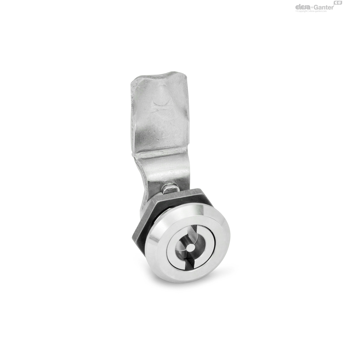
- Type VDE: With double bit
Lock housing
Stainless steel AISI 303 NI
Latch arm
Stainless steel AISI 304
Other parts
Stainless steel AISI 304
Protection class IP 65
Version in Stainless Steel (A4)
Types
- Type DK: With triangular spindle
- Type VK7: With square spindle
- Type VK8: With square spindle
- Type VDE: With double bit
Lock housing
Stainless steel AISI 316Ti A4
Latch arm
Stainless steel AISI 316
Other parts
Stainless steel AISI 316
Protection class IP 66
Information
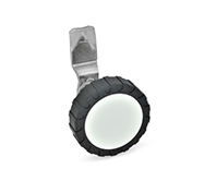
Latches GN 115-WSK-SST lock by a turning operation limited to 90° which moves the latch arm in the locked position behind the door frame. The bevels of the latch arm ease the closing of the door. Thanks to the stainless steel materials used, the latches are optimally suited for use in corrosive environments.
Latch arms are available with different bend angles to cover a latch arm distance A from 6 to 50 mm (version NI) and from 6 to 28 mm (version A4).
Latches GN 115-WSK-SST are supplied with loosely enclosed latch arm.
Accessory
- Socket Keys GN 119.2
- Protective Caps GN 120
- Opening Handles GN 120.1
- Protective Guide Plates GN 120.2
- Internal Cabinet Handles GN 120.3
- Sheet Metal Punches GN 123
On request
- Other operations
Technical information
- List of latch types
- IP Protection Classes
- Stainless Steel Characteristics
Construction and assembly instructions
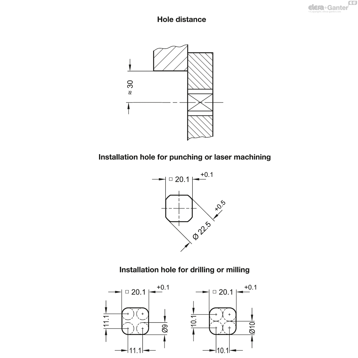
For installation, set a hole in the door, cover or hatch as shown in the outline drawing.
Once assembled, the latch is pushed through the bore diameter from the front. The hex nut can then be pushed over the latch from the back and bolted in place.
The required installation bore in the door leaf, is usually generated by punching or laser machining in series production.
The installation bore diameter can also be created by drilling or milling as shown in the outline drawings.
For small series and steel sheets below 2 mm thickness, the sheet metal punches GN 123 are the tool of choice.
GN 115-WSK-SST-A4
| Color | Latch arm distance A |
|||
|---|---|---|---|---|
| Code | Actions | |||
| GN 115-DK-6-A4 | DK | 6 | 91 |
|
| GN 115-DK-10-A4 | DK | 10 | 89 |
|
| GN 115-DK-14-A4 | DK | 14 | 88 |
|
| GN 115-DK-18-A4 | DK | 18 | 88 |
|
| GN 115-DK-20-A4 | DK | 20 | 89 |
|
| GN 115-DK-22-A4 | DK | 22 | 89 |
|
| GN 115-DK-24-A4 | DK | 24 | 89 |
|
| GN 115-DK-26-A4 | DK | 26 | 90 |
|
| GN 115-DK-28-A4 | DK | 28 | 91 |
|
| GN 115-VDE-6-A4 | VDE | 6 | 94 |
|
| GN 115-VDE-10-A4 | VDE | 10 | 92 |
|
| GN 115-VDE-14-A4 | VDE | 14 | 91 |
|
| GN 115-VDE-18-A4 | VDE | 18 | 91 |
|
| GN 115-VDE-20-A4 | VDE | 20 | 92 |
|
| GN 115-VDE-22-A4 | VDE | 22 | 92 |
|
| GN 115-VDE-24-A4 | VDE | 24 | 92 |
|
| GN 115-VDE-26-A4 | VDE | 26 | 93 |
|
| GN 115-VDE-28-A4 | VDE | 28 | 94 |
|
| GN 115-VK7-6-A4 | VK7 | 6 | 91 |
|
| GN 115-VK7-10-A4 | VK7 | 10 | 89 |
|
| GN 115-VK7-14-A4 | VK7 | 14 | 88 |
|
| GN 115-VK7-18-A4 | VK7 | 18 | 88 |
|
| GN 115-VK7-20-A4 | VK7 | 20 | 89 |
|
| GN 115-VK7-22-A4 | VK7 | 22 | 89 |
|
| GN 115-VK7-24-A4 | VK7 | 24 | 89 |
|
| GN 115-VK7-26-A4 | VK7 | 26 | 90 |
|
| GN 115-VK7-28-A4 | VK7 | 28 | 91 |
|
| GN 115-VK8-6-A4 | VK8 | 6 | 91 |
|
| GN 115-VK8-10-A4 | VK8 | 10 | 89 |
|
| GN 115-VK8-14-A4 | VK8 | 14 | 88 |
|
| GN 115-VK8-18-A4 | VK8 | 18 | 88 |
|
| GN 115-VK8-20-A4 | VK8 | 20 | 89 |
|
| GN 115-VK8-22-A4 | VK8 | 22 | 89 |
|
| GN 115-VK8-24-A4 | VK8 | 24 | 89 |
|
| GN 115-VK8-26-A4 | VK8 | 26 | 90 |
|
| GN 115-VK8-28-A4 | VK8 | 28 | 91 |
|

Enquiry Now
To allow us to respond to your enquiry promptly, please provide all required information.
Related Products
-
 GN 115-WOE-ZDLatcheswith Operating ElementsView Product
 -
 GN 115.1LatchesSmall Type, Operation with Socket Key / with Wing Knob, with and without LockView Product
 -
 GN 115-WOE-SSTLatchesStainless Steel, with Plastic Operating Elements / with Operating Elements in Stainless SteelView Product
 -
 GN 115-WOE-LLatchesZinc Die Casting / Stainless Steel, with Operating Elements, LockableView Product
 -
 GN 115-WSK-ZDLatchesOperation with Socket KeysView Product

