GN 1050
Quick Release Couplings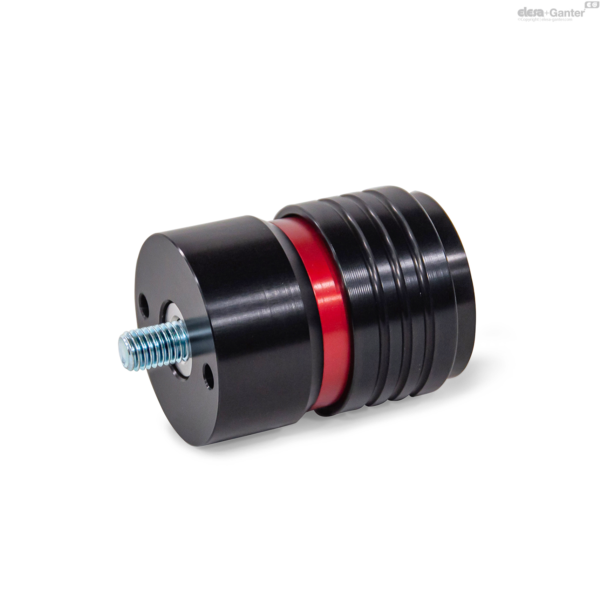
GN 1050-A
Quick Release Couplings
With threaded stud
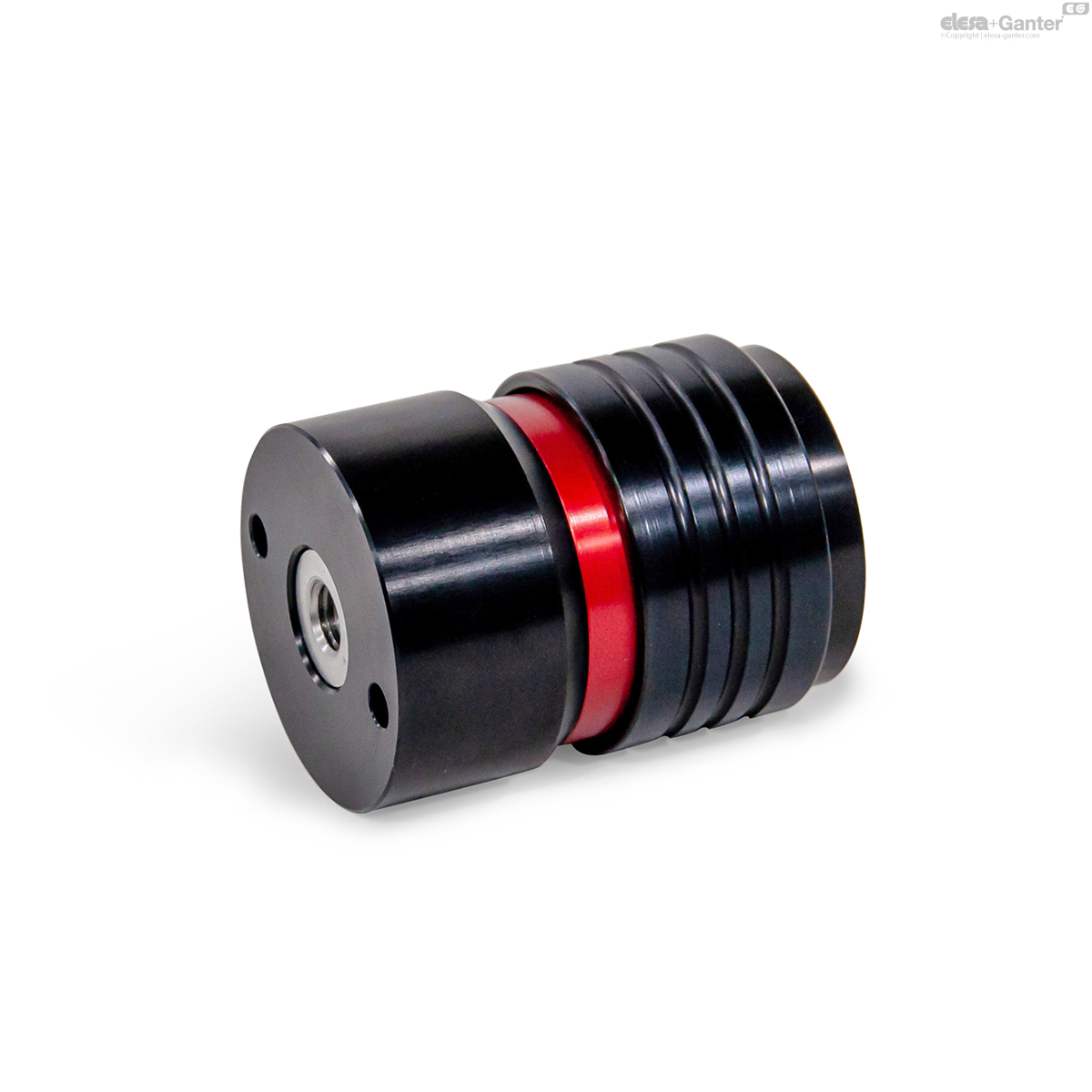
GN 1050-I
Quick Release Couplings
With internal thread
Description
Specification
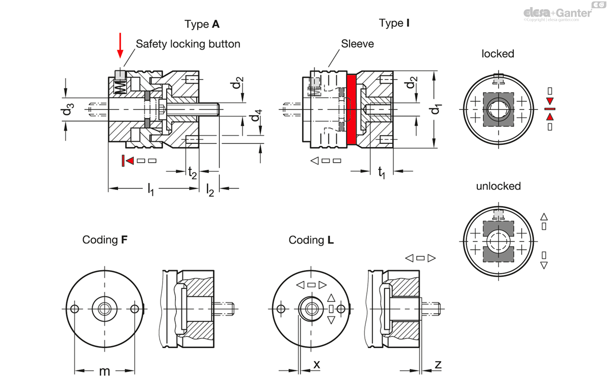
Types
- Type A: With threaded stud
- Type I: With internal thread
Coding
- F: Fixed bearing
- L: Floating bearing
Housing
Aluminum
Black anodized ASS
Closure mechanism
Steel, tempered
Zinc plated, blue passivated
Fastening bushing (type I)
Stainless steel AISI 431
Tempered
Mounting screw (type A)
Socket cap screw DIN 7984
Property class 8.8
Other screws
Steel, zinc plated, blue passivated
Other parts
Stainless steel
Operating temperature -30 °C to 120 °C
Information
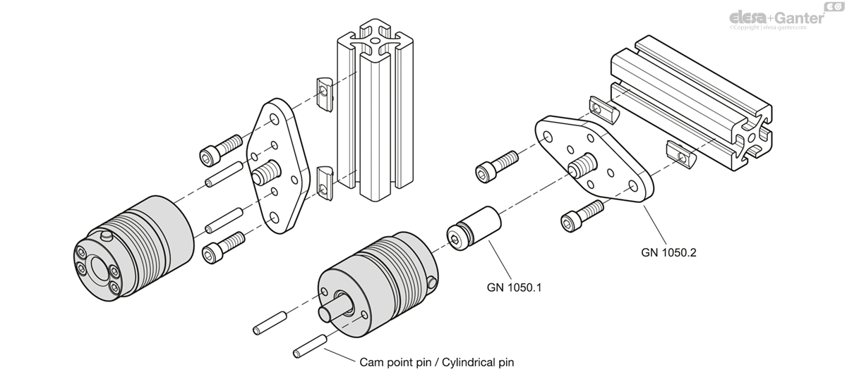
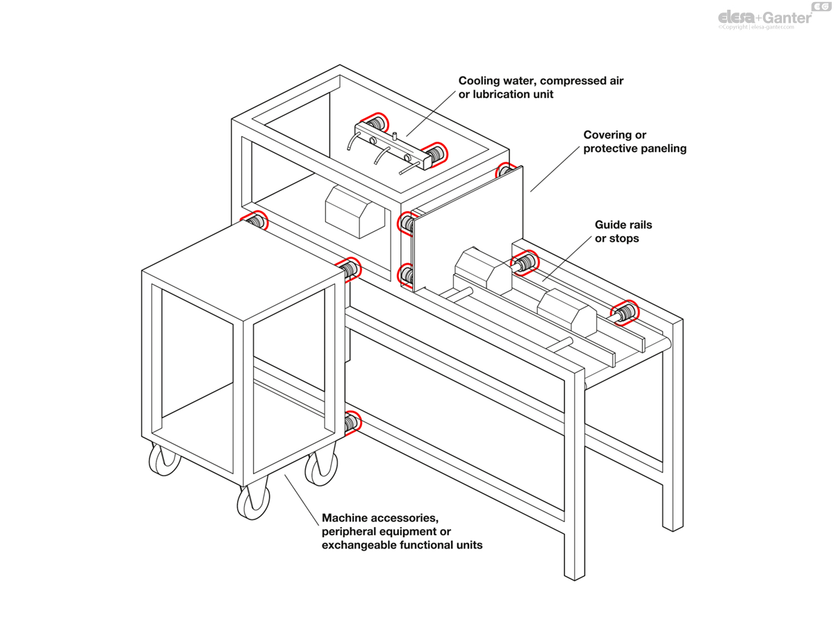
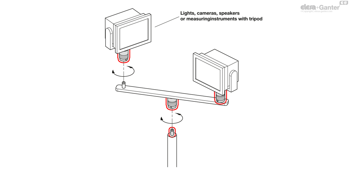
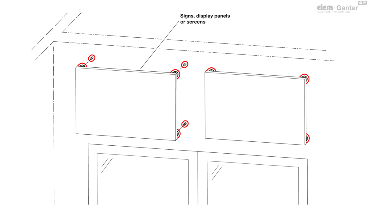
Quick release couplings GN 1050 position and connect components without tools using studs GN 1050.1 for a tight and repeatable fit. For repeated machine set ups or assemblies that require the inconvenient use of a screwdriver, quick release couplings can be used on fixtures or production lines to efficiently mount guide rails, covers or additional devices.
A safety locking button protects against accidental opening of the coupling. When pressing the button, the sleeve can be moved axially to unlock a stud inserted into the notch on the inside. At the same time, a red ring becomes visible on the outside to indicate the unlocked state.
The couplings do not transmit any torque. If multiple couplings are used on the same unit, coding L can be used to compensate for a radial and axial offset. The bores d4 can hold cylinder or cam point pins to position the coupling, if needed. For coding L, the pin holes on the application must be proportionally larger to allow for radial adjustments.
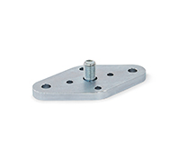
Flanges GN 1050.2 are available as an accessory for the assembly of couplings and studs, and provide additional attachment options.
Accessory
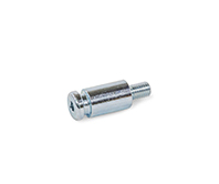
- Studs GN 1050.1
- Flanges GN 1050.2
On request
- Other colors (anodized) or plain
Technical information
- Stainless Steel characteristics
- Strength values of screws / nuts
Mounting and load information
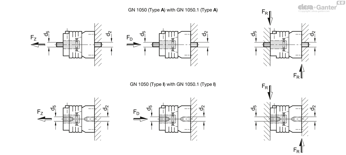
| Nominal Size | d2 Mounting thread Quick release couplings | d5 Mounting thread Studs GN 1050.1 | FZ Max. tensile load in kN | FD Max. compressive load in kN | FRMax. shear load in kN |
| 2N | M 10 | M 10 | 25 | 25 | 19 |
| 2N | M 10 | M 12 | 25 | 25 | 19 |
| 2N | M 12 | M 10 | 25 | 25 | 19 |
| 2N | M 12 | M 12 | 35 | 35 | 28 |
Safety instructions:
The load capacities can only be achieved if the surrounding structure is capable of supporting these loads.
Any threaded holes on the application or inserted nuts and screws require at least property class 8.
Depending on the application, additional safety factors should be added.
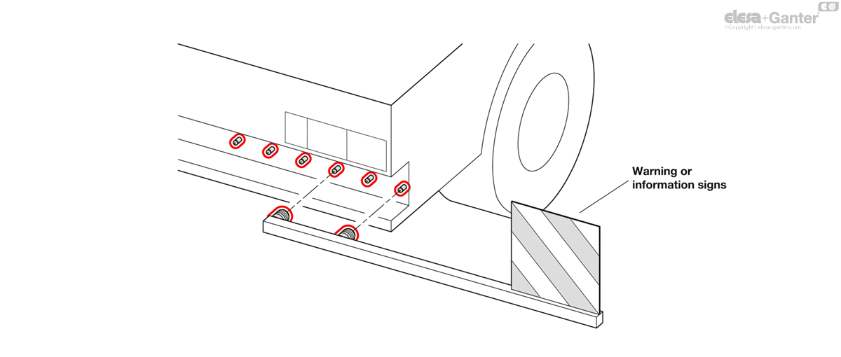
Application example for profile systems
Application Examples
GN 1050-I
Nominal size |
d2 | d1 | x +0.05 Radial offset | d3 Bore ±0.03 |
d3 Studs GN 1050.1 ±0.03 | d4 H7 | l1 | m | t1 min. | t2 | z ±0.1 Axial offset | |||
|---|---|---|---|---|---|---|---|---|---|---|---|---|---|---|
| Code | Actions | |||||||||||||
| GN 1050-2N-M10-I-F-ASS | 2N | M 10 | 53 | - | 18.5 | 18.25 | 6 | 70.1 | 40 | 18 | 10 | - | 407 |
|
| GN 1050-2N-M10-I-L-ASS | 2N | M 10 | 53 | 0.75 | 18.5 | 18.25 | 6 | 70.1 | 40 | 18 | 10 | 0.4 | 404 |
|
| GN 1050-2N-M12-I-F-ASS | 2N | M 12 | 53 | - | 18.5 | 18.25 | 6 | 70.1 | 40 | 18 | 10 | - | 403 |
|
| GN 1050-2N-M12-I-L-ASS | 2N | M 12 | 53 | 0.75 | 18.5 | 18.25 | 6 | 70.1 | 40 | 18 | 10 | 0.4 | 397 |
|

Enquiry Now
To allow us to respond to your enquiry promptly, please provide all required information.