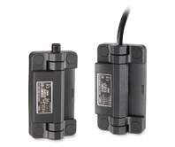
ESC-SFT
Handles with built-in safety switch
Technopolymer
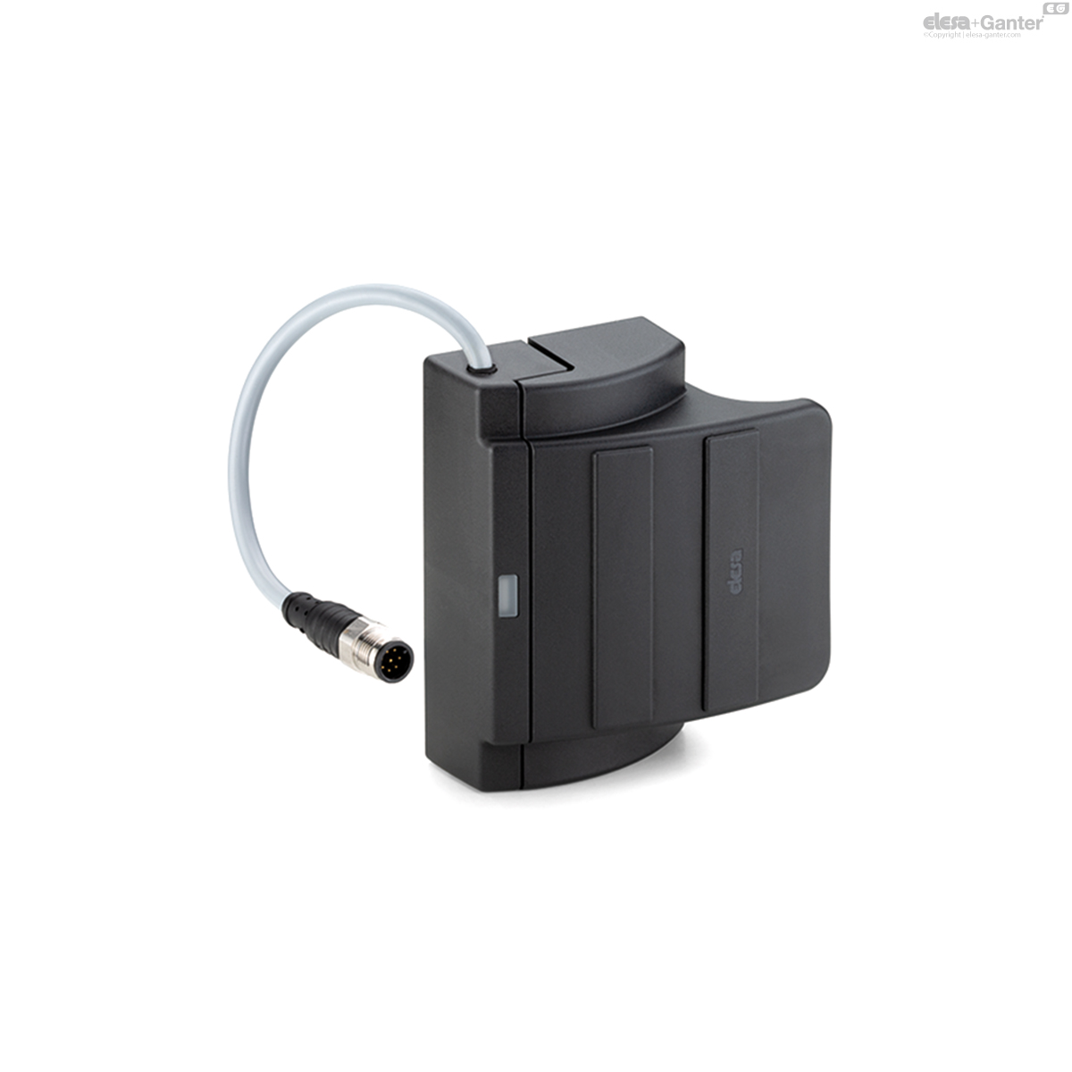
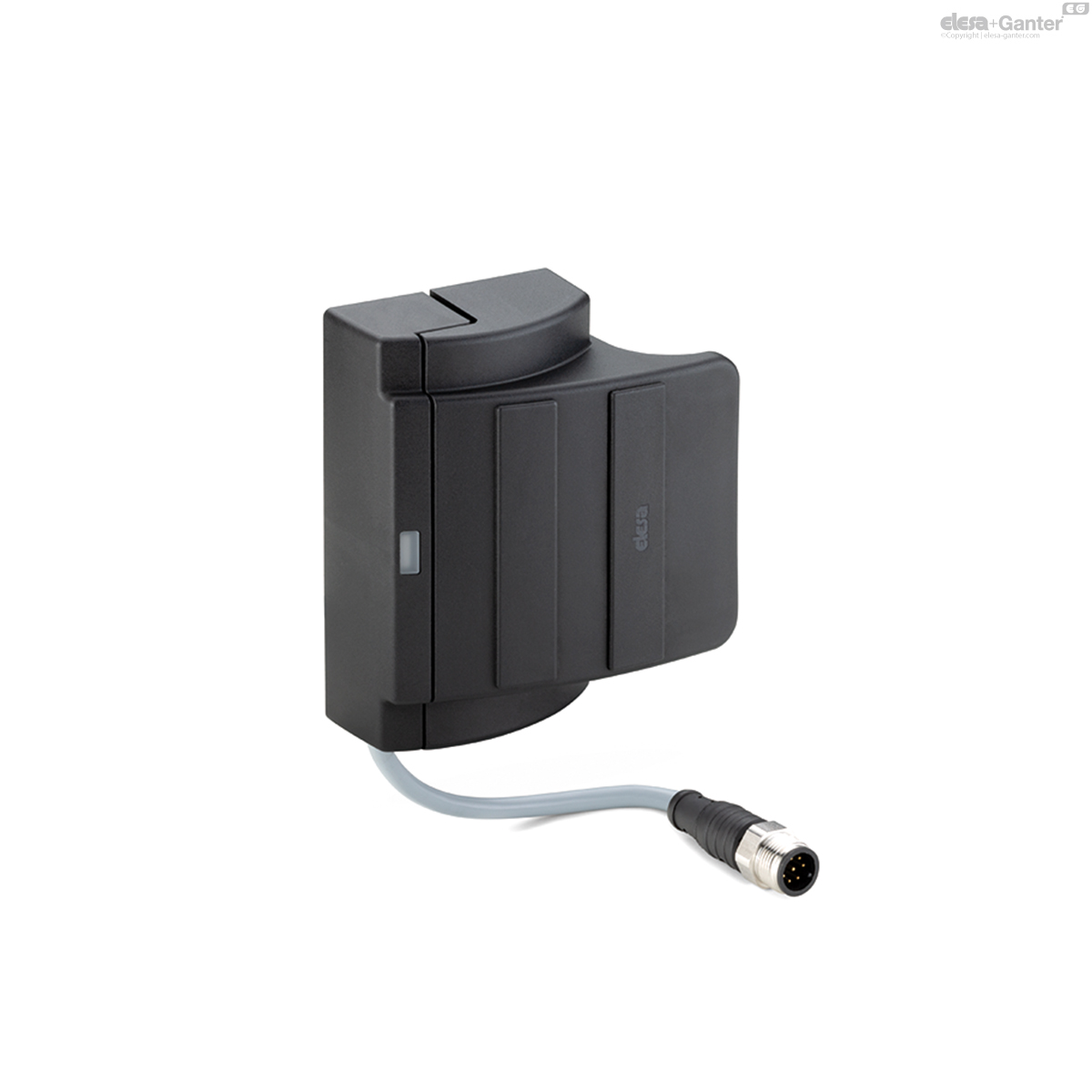
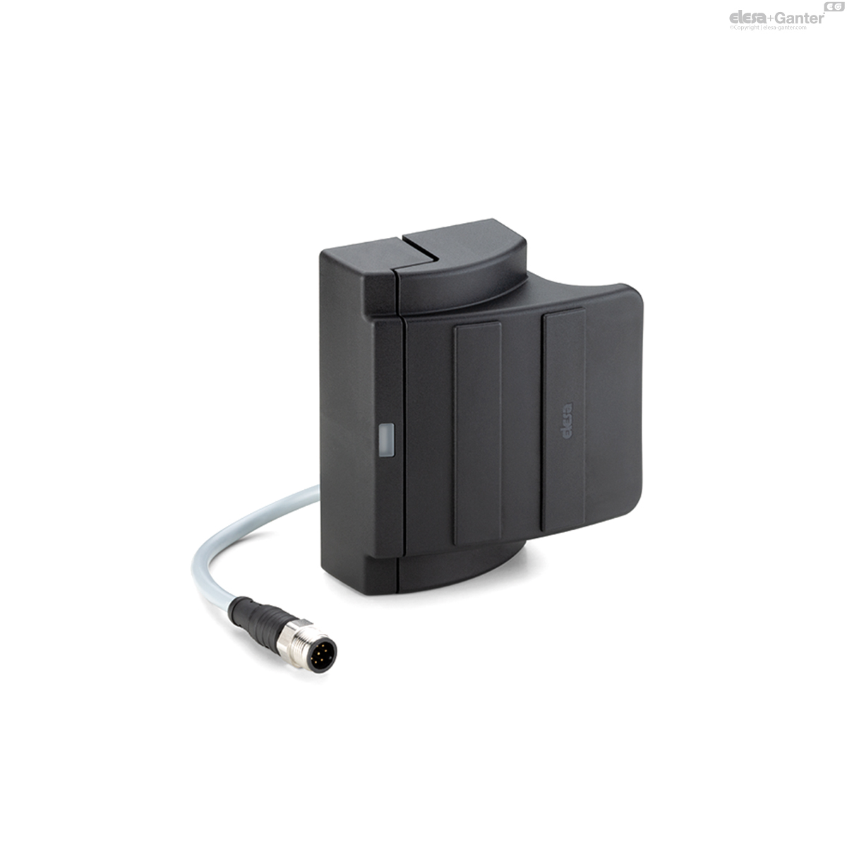
ESC-SFT-C-A
Handles with built-in safety switch
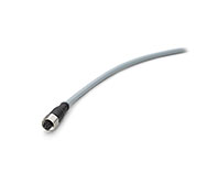
8 pole male connector, top axial output
ESC-SFT-C-C
Handles with built-in safety switch
8 pole male connector, bottom axial output
ESC-SFT-C-B
Handles with built-in safety switch
8 pole male connector, back output
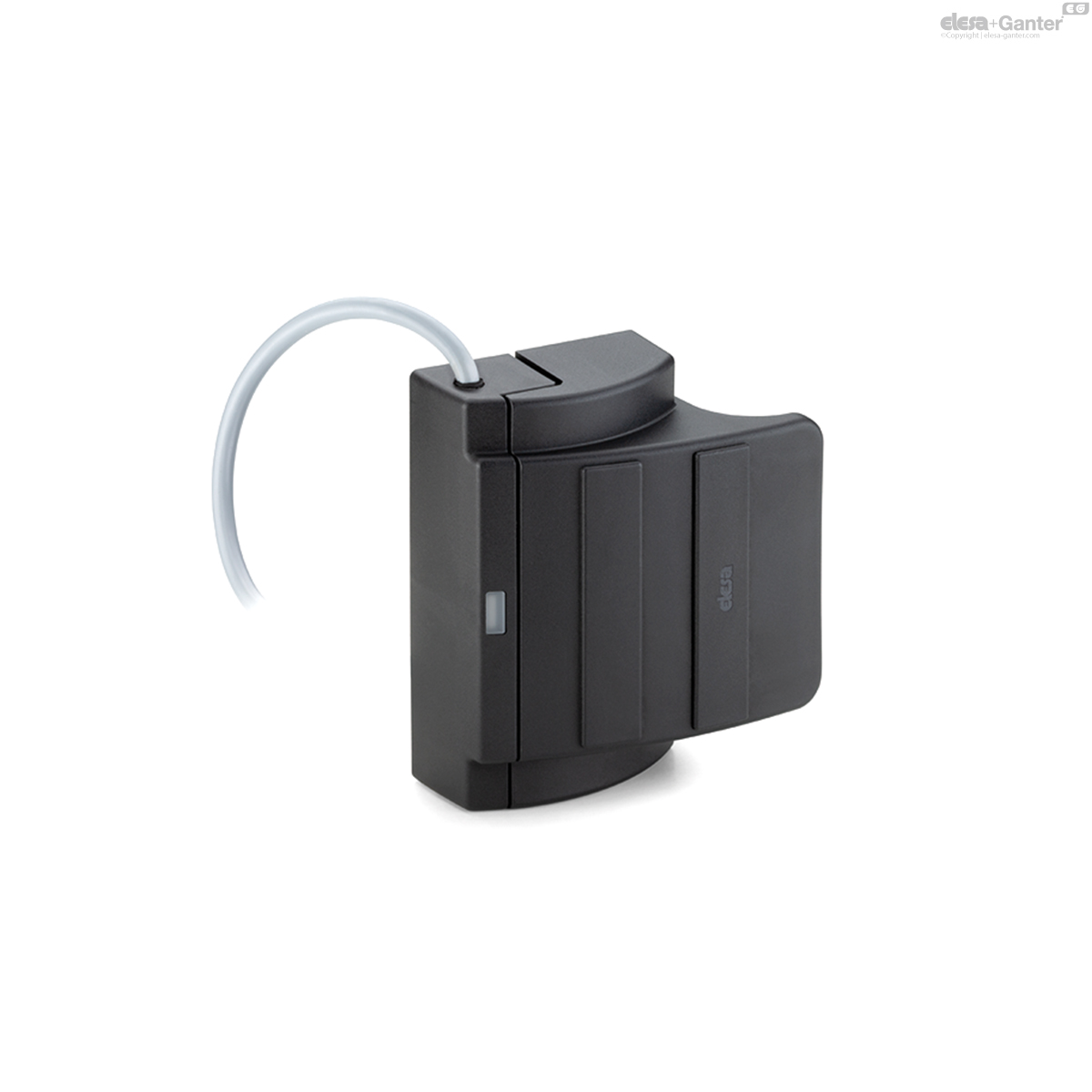
ESC-SFT-F-A
Handles with built-in safety switch
Cable length 2 or 5 metres, top axial output
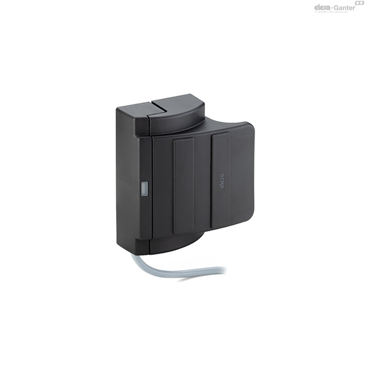
ESC-SFT-F-C
Handles with built-in safety switch
Cable length 2 or 5 metres, bottom axial output
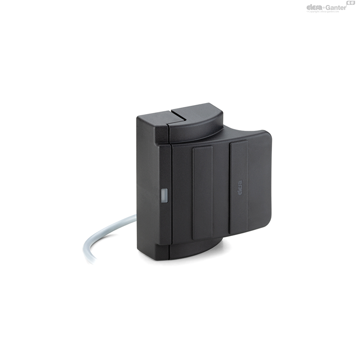
ESC-SFT-F-B
Handles with built-in safety switch
Cable length 2 or 5 metres, back output


Description
Main specifications
Material
- Handle body: glass-fibre reinforced polyamide based (PA) technopolymer, certified self-extinguishing UL-94 V0, black colour.
- Clamp element: acetal-based technopolymer (POM), black colour.
- Screw cover: glass-fibre reinforced polyamide based (PA) technopolymer, certified self-extinguishing UL-94 V0, black colour.
- LED light diffusor: UL-94 V0 self-extinguishing polycarbonate, opal colour.
- Fixing plates: stainless steel.
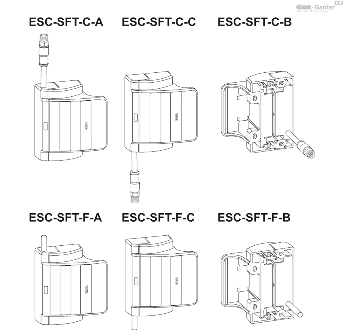
Standard executions
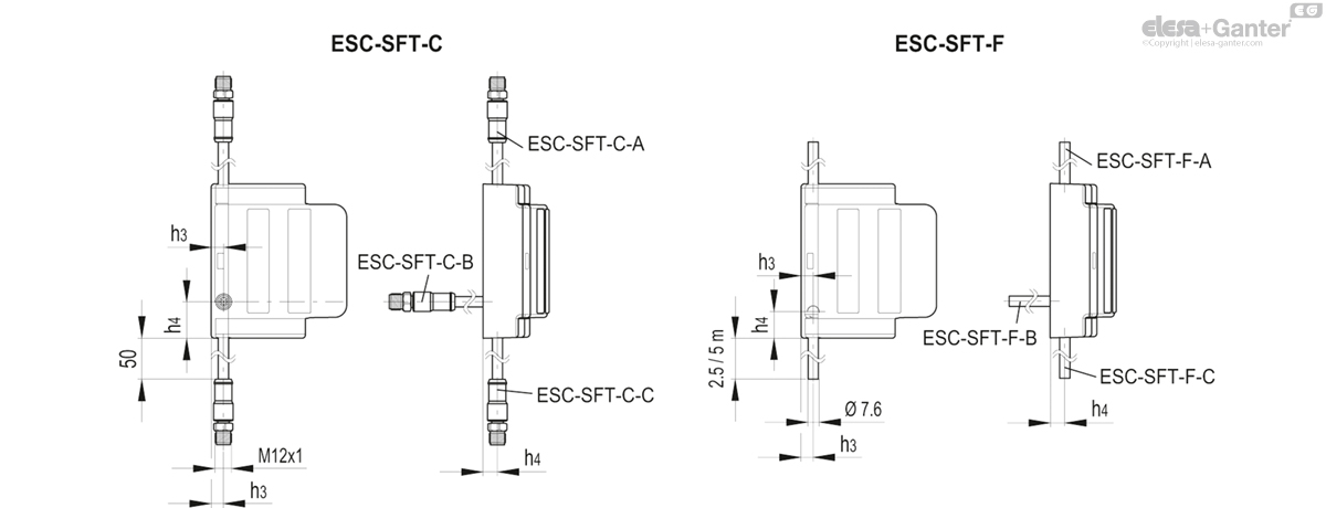
- ESC-SFT-C-A: 8 pole male connector M12, top axial output.
- ESC-SFT-C-C: 8 pole male connector M12, bottom axial output.
- ESC-SFT-C-B: 8 pole male connector M12, back output.
- ESC-SFT-F-A: cable length 2 or 5 metres, top axial output.
- ESC-SFT-F-C: cable length 2 or 5 metres, bottom axial output.
- ESC-SFT-F-B: cable length 2 or 5 m, back output.
The ESC-SFT handle must be mounted with the matching part side equipped with a cable/connector exit on the fixed part (structure chassis) and with the handle side on the mobile part (door).
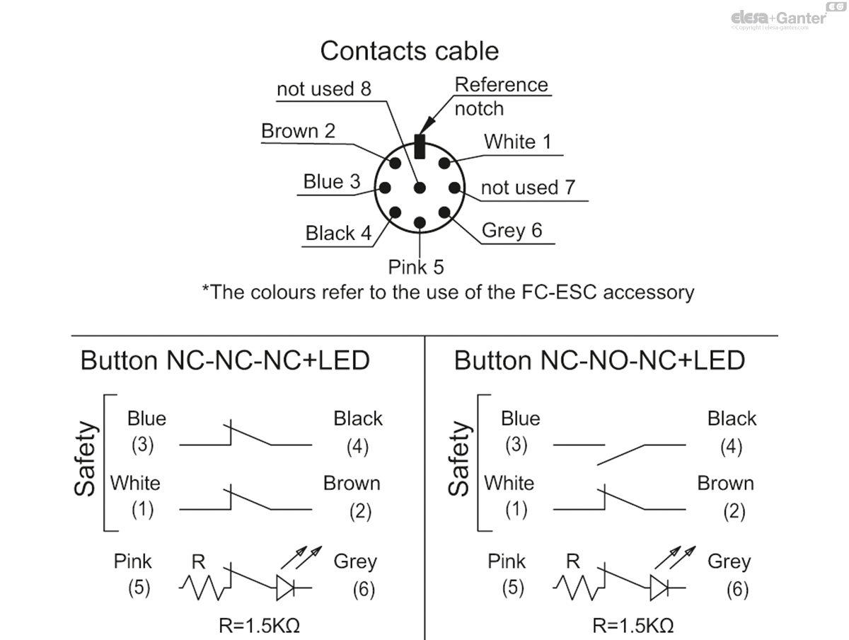
Contact blocks in the standard execution:
- NC-NO-NC+LED: 1 NC safety contact, 1 NO safety contact, 1 NC signalling contact with LED.
- NC-NC-NC+LED: 2 NC safety contacts, 1 NC signalling contact with LED.
NO contact is considered to be the normally open contact when the two elements of the handle are in contact, while NC contact is the normally closed contact when the two elements of the handle are in contact.
The green LED is on when the protection is closed (two elements of the handle contact) and indicates the correct functioning of the machinery in accordance with IEC 60204-1.
IP protection
IP67 protection class, see Table EN 60529.

General information
Features and applications
Staff protection: the ESC-SFT handle is a coded sensor with redundant channels that can be used in safety circuits designed to monitor the status of dangerous guards on board the machine. In combination with an appropriate certified control logic, in the case of accidental opening of doors, casings, protective covers of machinery or production lines, it activates the interruption of the machinery's power circuit. The interlocking device consists of a magnetic sensor and the corresponding actuator (coded magnet), incorporated into the two elements of the handle. The approach of the coded magnet to the sensor involves the switching of the contacts inside the sensor and the relative closure of the safety outputs of the control unit connected to it. A green LED is on when the two elements of the handle are in contact and the guard is closed. The ESC-SFT handle is classified as a low coding level type 4 magnetic interlock device in accordance with EN14119. If used as an input to a certified safety control unit (see accessories on request), it permits a system architecture up to SIL3 in accordance with the IEC 62061 standard or category 4 - PLe in accordance with the EN ISO 13849-1 standard. It can be associated with the CFSQ or CFSW hinge to increase the system safety level (systems with different operating principles). The switching distance of the sensors is independent of the geometry of the door on which the product is installed.
Snap lock: the two parts that make up the product (handle side and matching part side) are equipped with a mechanical coupling system that allows the door to remain closed. The opening force required to open the door is approximately 2 kg.
Self-centring: the handle is fitted with a mechanical self-centring system with respect to its matching part which compensates for any misalignment of the door or bending of it due to the weight. It can be used for sliding or swing doors.
Functioning
The safety system is composed of a control unit and a handle, which works only in particular configurations (see the combination and wiring options with the respective combined safety control units)
The safety handle contains reed contacts that are activated by coded magnets. The safety control unit converts the information and transfers the state of the protections to the control system via a safety output.
The safe state is defined as the state in which the handle is away from its activation magnet.
| HANDLE TECHNICAL DATA | ||||
|---|---|---|---|---|
| GENERAL FEATURES | ||||
| Housing material | Black glass-fibre reinforced self-extinguishing technopolymer | |||
| Operating room temperature | -25 +70 °C | |||
| Protection class | IP 67 (IEC 60529) | |||
| Connections | Cable with ferrules - M12 male connector | |||
| Operational voltage (Ue) | 24 V dc | |||
| Minimum operating current per channel (Im) | 6 mA | |||
| Maximum operating current with LED in the absence of load | 16 mA | |||
| Current in the Off state | 0 mA | |||
| Insulation voltage (Ui) | 26,4 V | |||
| Rated withstand voltage (Ui) | 1500 V | |||
| Pollution degree | 2 | |||
| Fast external fuse | 0,5 A | |||
| Category of usage | DC12: 0,4A at 24Vdc - DC13: 0,4A at 24Vdc | |||
| Max. switching frequency | 500 Hz | |||
| Voltage drop (Ud) | 0,3 V | |||
| Switching indication | Green LED + NC signalling output (24V, 10mA) | |||
| ACTIVATION PARAMETERS | ||||
| Handle Options (sliding door S, swing door B) | NC+NO S | NC+NC S | NC+NO B | NC+NC B |
| Guaranteed intervention distance (Sao) | 3 mm | 5 mm | 6 mm | 9 mm |
| Guaranteed release distance (Sar) | 13 mm | 17 mm | 17 mm | 20 mm |
| Repetition accuracy | <10% | <10% | <10% | <10% |
| RELIABILITY/SAFETY FUNCTIONAL PARAMETERS | ||||
| B10d (EN 13849-1) | 20x10^6 cycles | |||
| TM | 20 years | |||
| Diagnostic coverage (DC) | Sent to the control unit | |||
| Disabling time | <10 ms | |||
| Risk time | Sent to the control unit | |||
| PL/category in accordance with EN13849-1 | up to Pl e/Cat.4 (in combination with the safety modules CN-SFT.115-2NC, CN-SFT.46-2NC/CN-SFT.115-1NC+1NO, CN-SFT.46-1NC+1NO or other comparable safety control units) | |||
| Coding EN ISO 14119:2013 | Type 4 (low coding level) | |||
| CONFORMITY | ||||
| Resistance to vibrations and shocks | EN60947-5-3 | |||
| Product conformity | EN60947-5-3 EN14119 | |||
| Approved by TUV | TUV IT 0948 24 MAC 429 BTUV IT 0948 24 MAC 428 B | |||
| Approved by UL | E542642 | |||
Electrical connections
Electrical connections
Electrical connections must only be carried out by authorised personnel.
The sensor connection cable must not be stretched out. The sensors must be connected to the control unit according to the suggested diagrams (see also the operating instructions for the control units).
| Cabling in accordance with Standard 60947-5-2 | ||
| Colour | Type | Function |
| Brown (BN) - White (WH) | NC contact | safety outputs Channel 1 |
| Blue (BU) - Black (BK) | NC contact (vers. NC+NC) | safety outputs Channel 2 |
| NO contact (vers. NC+NO) | ||
| Pink (PK) | Auxiliary contact positive (+24Vdc) | Positive for LED signalling |
| Grey (GY) | Auxiliary contact negative (GND) | Negative for LED signalling |

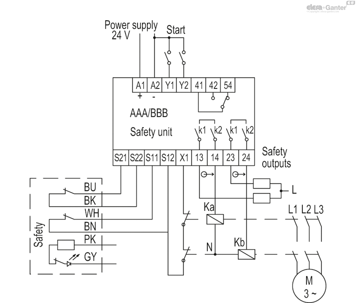
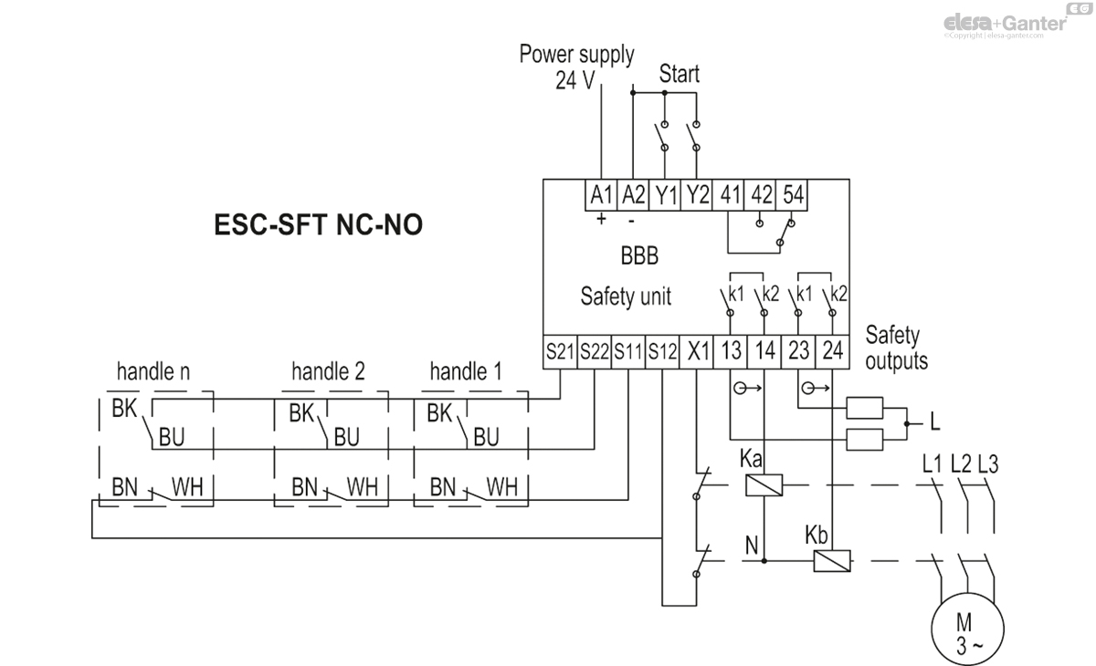
Connection diagram of a single handle to the CN-SFT.115-2NC, CN-SFT.46-2NC / CN-SFT.115-1NC+1NO, CN-SFT.46-1NC+1NO control units or equivalent models. The handle with NC-NC contacts must be connected to the CN-SFT.115-2NC / CN-SFT.46-2NC control unit, the handle with NC-NO contacts must be connected to the CN-SFT.115-1NC+ 1NO / CN-SFT.46-1NC+1NO control unit. In any case, it is advisable to read the safety control unit instruction manual to verify the correct wiring of the product.

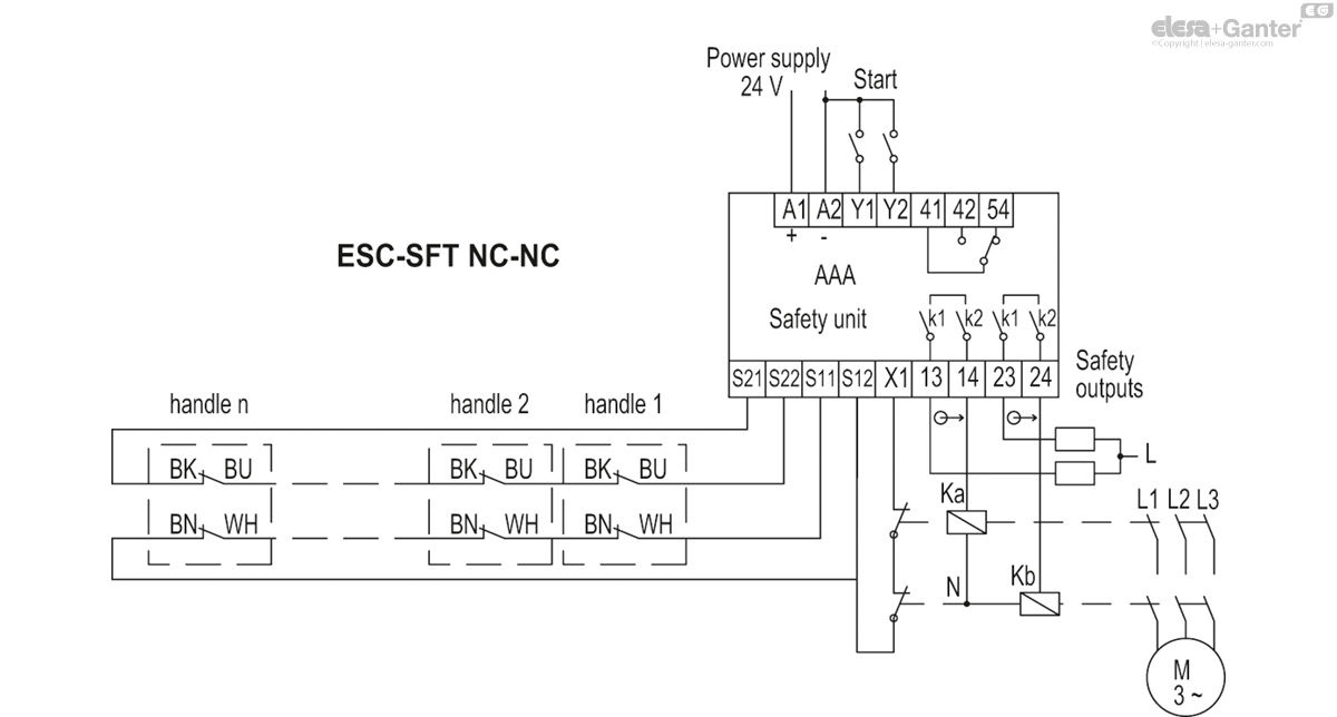
Connection diagram of a single handle to the CN-SFT.115-2NC / CN-SFT.46-2NC control units or equivalent models in the case of multiple handles with NC-NC contacts.
- Channels 1 (BU-BK, NC) in series
- Channels 2 (WH-BN, NC) in series
In any case, it is advisable to read the safety control unit instruction manual to verify the correct wiring of the product.
Connection diagram of a single handle to the CN-SFT.115-1NC+1NO / CN-SFT.46-1NC+1NO control units or equivalent models in the case of multiple handles with NC-NO contacts.
- Channels 1 (BU-BK, NO) in parallel
- Channels 2 (WH-BN, NC) in series
In any case, it is advisable to read the safety control unit instruction manual to verify the correct wiring of the product.

Accessories
Accessories on request
- CN-SFT: safety control unit for category 3 and 4.
- FC-ESC: extension length 2.5 or 5 m.
Assembly instructions
Assembly instructions
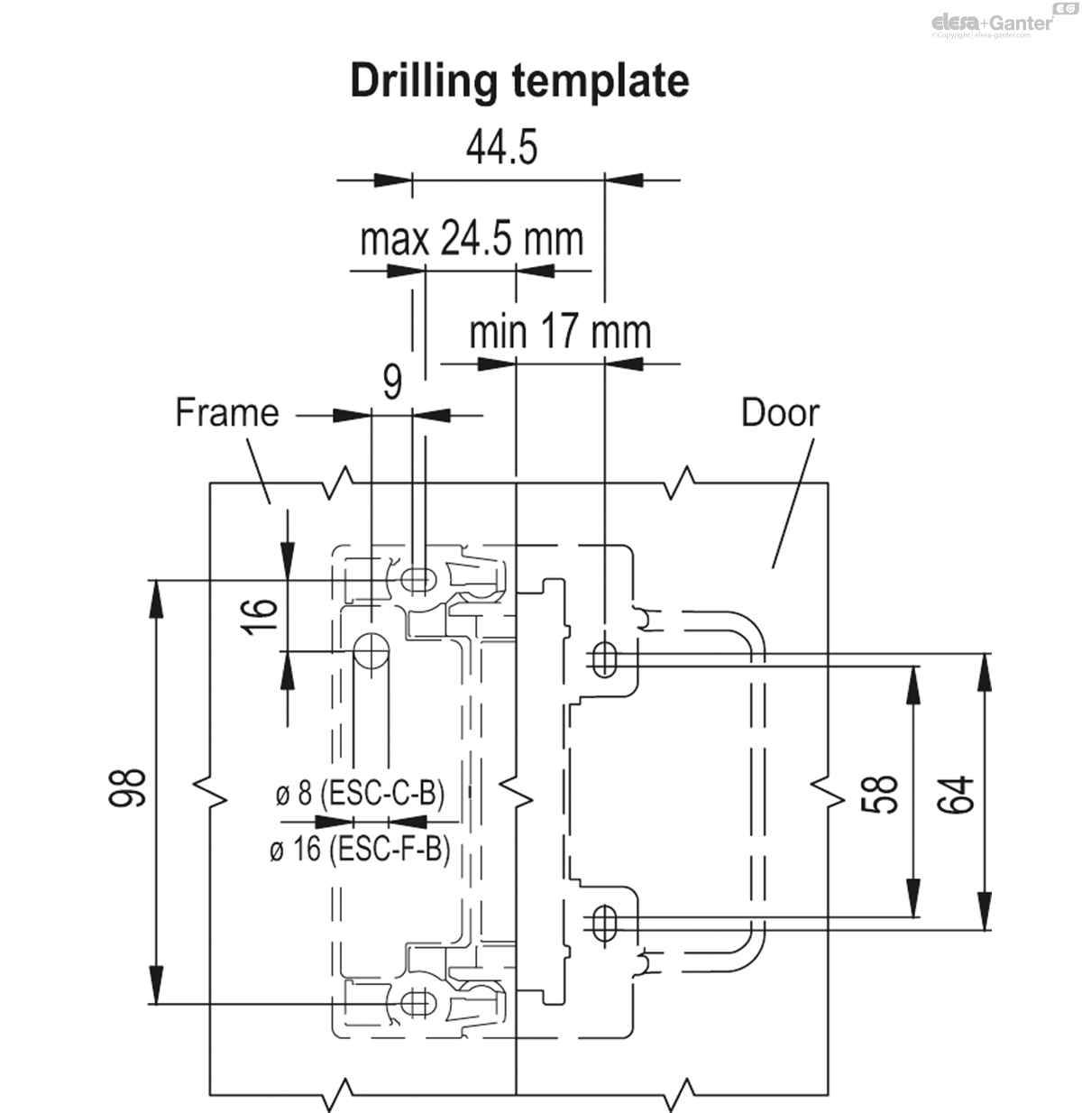
- Mount the handle matching part on the frame and the handle on the door, using the fixing plates (included in the supply) placing them between the TCEI M5 screws and the handle. The presence of slotted holes allows for easier installation of the product.
- Carry out the wiring according to the electrical diagram indicated.
- The use of an external fast fuse on the safety line is recommended.
- The product should not be used in an environment with strong magnetic fields.
- Assembly permitted only in the absence of voltage.
- Mounting position of choice, provided that the active surface of the safety sensor and that of the actuator are opposite each other.
- Only mount the sensor on flat surfaces.
- If possible, do not mount the sensor and actuator on surfaces made of ferromagnetic material. It is recommended to install a non-magnetic spacer with a thickness of at least 5 mm. It is also recommended to use non-magnetic fixing screws.
- Do not expose the sensor and actuator to strong vibrations and shocks.
- Keep away from iron residues.
- Leave a minimum mounting distance between two handles of 50 mm.
- For minimum distance between holes on the door side and frame, see drilling template.

Precautions
Precautions
Before using the product, a risk assessment must be carried out on the machine in accordance with:
- EN ISO 13849-1, Safety of machinery — Safety-related parts of control systems — Part 1: General principles for design;
- EN ISO 14119, Safety of machinery — Interlocking devices associated with guards;
- EN 60204-1, Safety of machinery - Electrical equipment of machines;
- EN 60947-5-3, Low-voltage switchgear and controlgear - Part 5-3: control circuit devices and switching elements - Requirements for proximity devices with defined behaviour under fault conditions (PDDB).
- The ESC-SFT handle performs a personal protection function. Incorrect installation or handling can cause serious damage to people. In particular, the handle must not be bypassed (short-circuiting the contacts), moved, removed or otherwise rendered ineffective.
- Safe operation is ensured only when the complete system, safety handle + control unit CN-SFT.115-2NC, CN-SFT.46-2NC/CN-SFT.115-1NC+1NO, CN-SFT.46-1NC+1NO or comparable is used. If the handle is used without a suitable control unit, the responsibility lies with the assembler of the system/machine.
- A complete safety system is generally composed of many signalling devices, sensors, control units. The manufacturer of the machine, or the installer, is responsible for correct and safe overall operation.
Maintenance and checks
Maintenance and checks
Remove any iron filings from the handle at regular intervals. Use only solvent-free detergents to clean the handle.
Additional safety measures (EN ISO 14119:2013, Table 3)
It is mandatory to periodically check (at the beginning of each shift at the latest within 8 hours) the correct functioning of the handles by inspecting the following:
- correct switching of each handle by checking:
a) that when the guard to which the handle is mounted opens, the safety outputs of the connected control unit are opened.
b) that when the same guard closes, the safety outputs of the control unit are closed following any start command.
- secure fixing of the handle.
- correct fixing of the connections.
The monitoring function of the device must be carried out by the safety control unit connected for each intervention of the device itself.
If, with all protections closed and following a possible start command, the control unit does not activate its safety outputs, avoid turning the control unit off and on and proceed to check for any open guards and carry out the checks indicated above in points a) and b).
In the event of failure or wear, the damaged system must be replaced.
The warranty coverage as well as the manufacturer's liability ceases in the following circumstances:
- if the instructions have not been followed.
- failure to comply with the safety regulations.
- electrical installation and connection not carried out by authorised personnel.
- failure to carry out operational checks.
- tampering with the product.
ESC-SFT-C-A
| L | f±0.25 | f1±0.25 | f2±0.25 | f3±0.25 | f4±0.25 | H | h1 | h2 | h3 | h4 | l1 | l2 | C# [Nm] |
||||
|---|---|---|---|---|---|---|---|---|---|---|---|---|---|---|---|---|---|
| Code | Description | Actions | |||||||||||||||
| 225041 | ESC-SFT.110-5-NC+NC-C-A | 114 | 98 | 64 | 58 | 44.5 | 41.5 | 49 | 5 | 39 | 7 | 15 | 100 | 69.5 | 5 | 318 |
|
| 225071 | ESC-SFT.110-5-NC+NO-C-A | 114 | 98 | 64 | 58 | 44.5 | 41.5 | 49 | 5 | 39 | 7 | 15 | 100 | 69.5 | 5 | 318 |
|

Enquiry Now
To allow us to respond to your enquiry promptly, please provide all required information.