

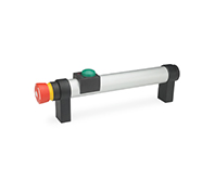
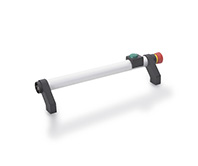
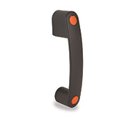
EBR-SWB
Handle with bistable electrical switch
Technopolymer
EBR-SWB-B-C
Handle with bistable electrical switch
Connector, back output
EBR-SWB-L-C
Handle with bistable electrical switch
Connector, left side output
EBR-SWB-R-C
Handle with bistable electrical switch
Connector, right side output
EBR-SWB-B-F2.5
Handle with bistable electrical switch
Cable, length 2.5 m, back output
EBR-SWB-B-F5
Handle with bistable electrical switch
Cable, length 5 m, back output
EBR-SWB-L-F2.5
Handle with bistable electrical switch
Cable, length 2.5 m, left side output
EBR-SWB-L-F5
Handle with bistable electrical switch
Cable, length 5 m, left side output
EBR-SWB-R-F2.5
Handle with bistable electrical switch
Cable, length 2.5 m, right side output
EBR-SWB-R-F5
Handle with bistable electrical switch
Cable, length 5 m, right side output


Description
Main specifications
Material
Glass-fibre reinforced polyamide based (PA) technopolymer, grey-black colour, matte finish.
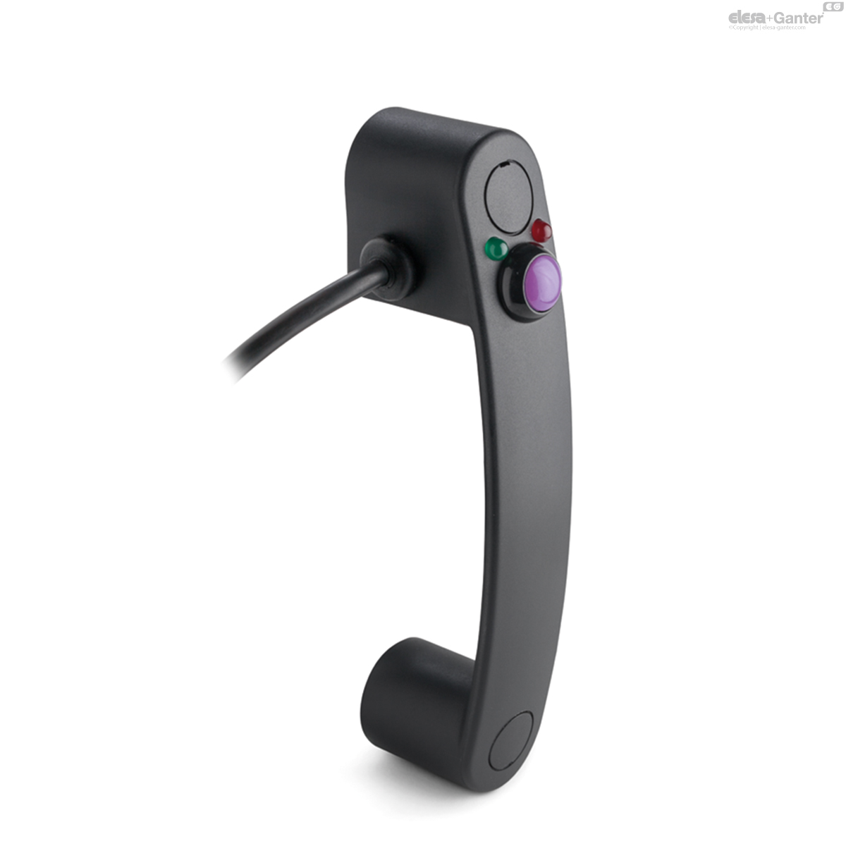
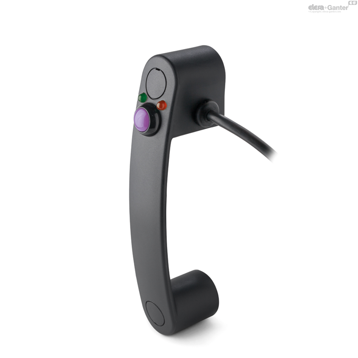
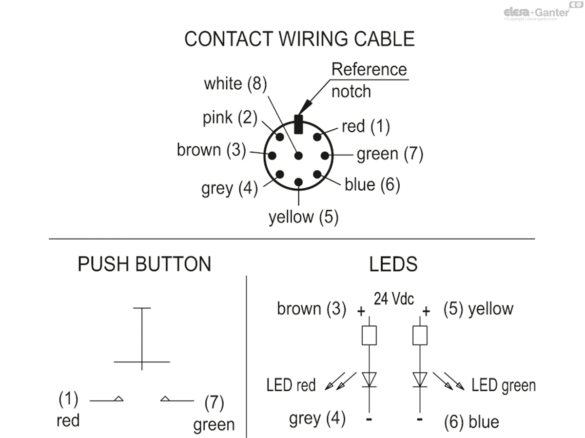
Microswitch with button
The device is made up of a bistable normally open contact (NO).
Switching takes place by pressing the purple button, and remains switched until pressed again.
Contact resistance: max. 0.050 Ω
Isolation resistance: min. 1 GΩ at 500 VDC
Led
A red Led and a green Led can be configured through external logic to indicate the switch status.
Voltage range 24 Vdc ± 15%
Screw-covers
Technopolymer, grey-black colour, matte finish. Supplied assembled, removable by a screwdriver.
IP protection
IP 65 protection class, according to EN 60529
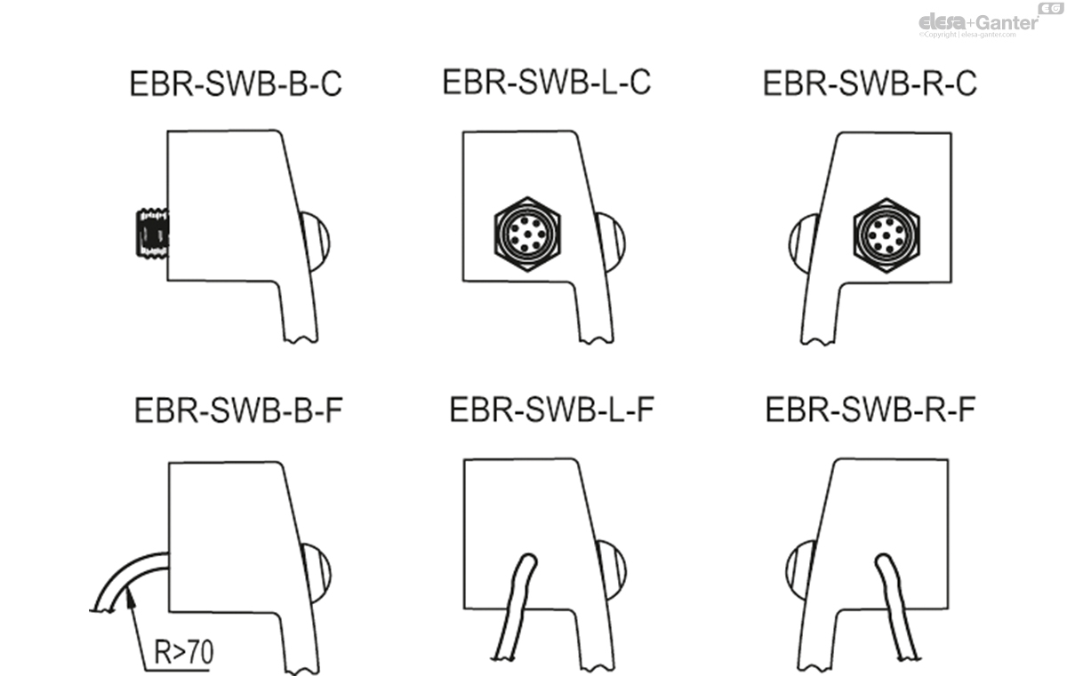
Standard executions
Pass-through holes for cylindrical-head screws with hexagon socket.
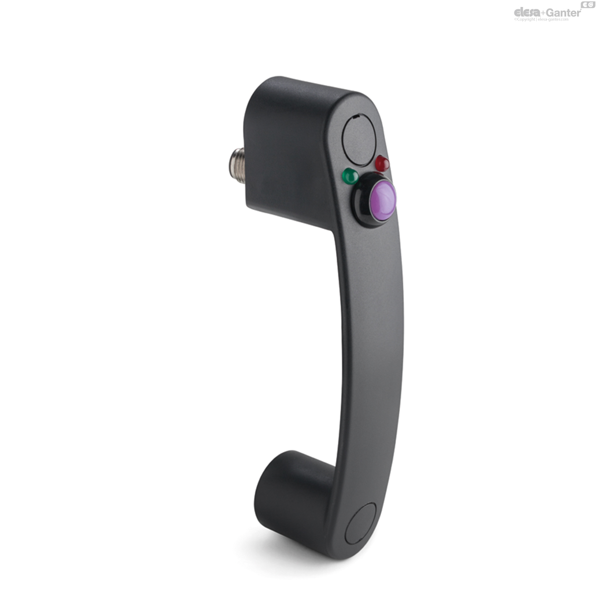
- EBR-SWB-B-C: zinc-plated connector with 8 poles, back output.
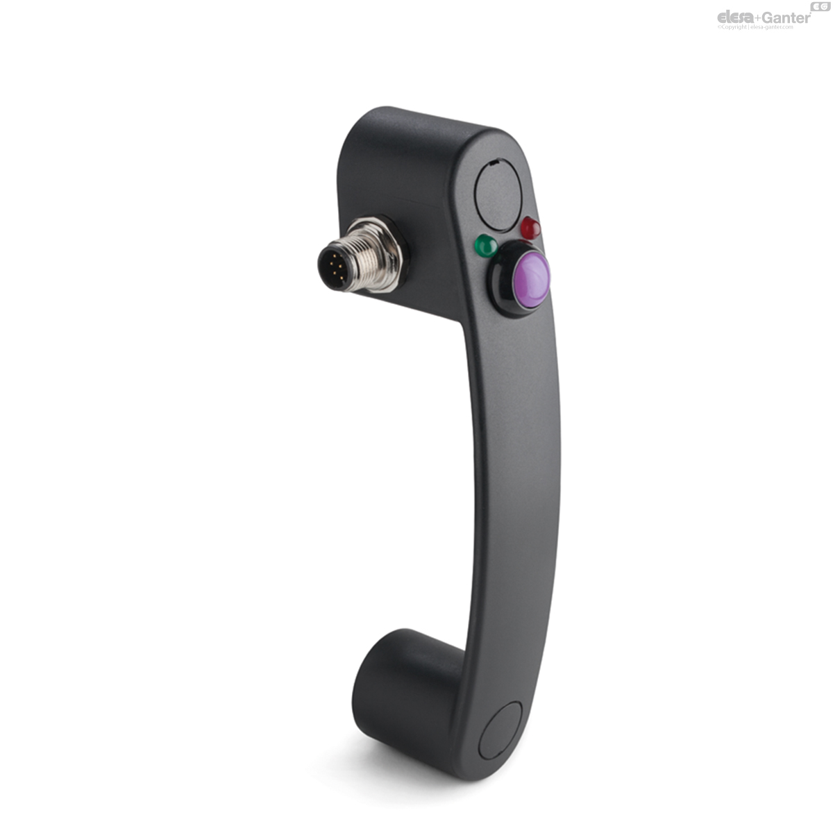
- EBR-SWB-L-C: zinc-plated steel connector with 8 poles, left side output.
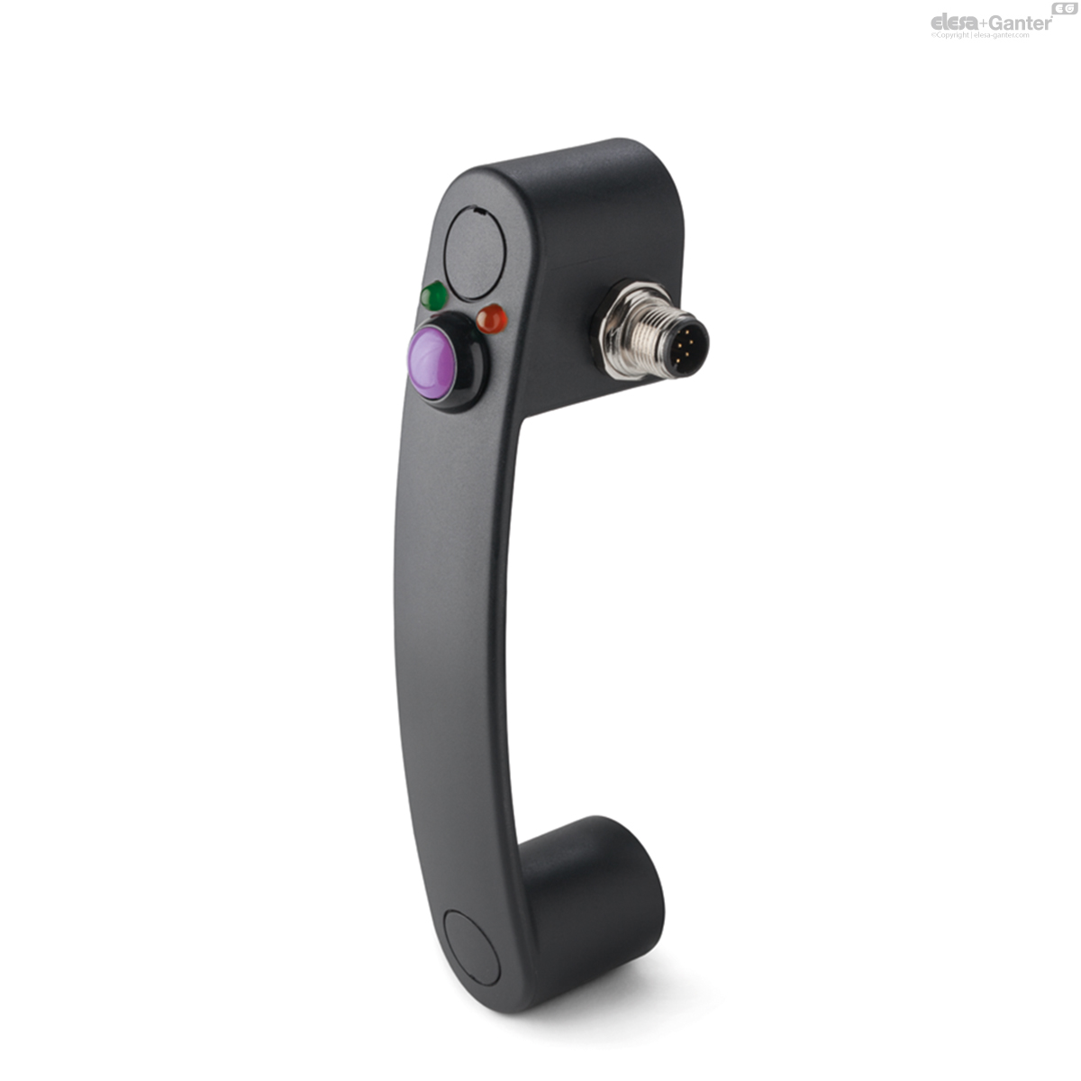
- EBR-SWB-R-C: zinc-plated connector with 8 poles, right side output.
8 pole cable UL: AWG22 RAL9005 PVC UL AWM Style 1569/2517.
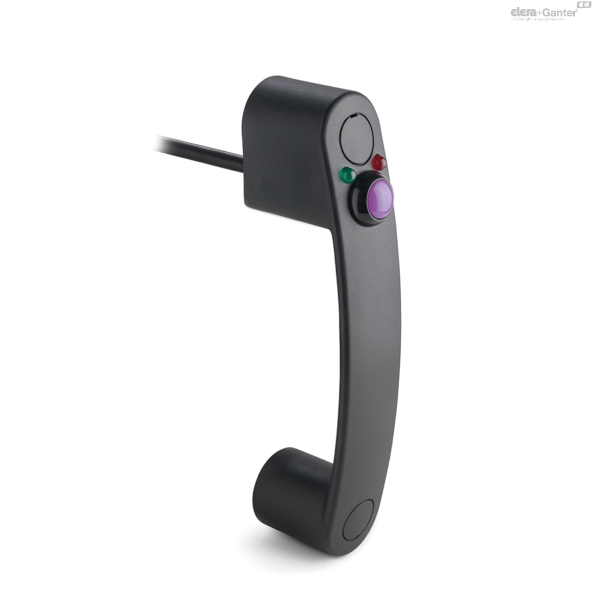
- EBR-SWB-B-F2.5: 8 pole cable, length 2.5 metres, back output.
- EBR-SWB-B-F5: 8 pole cable, length 5 metres, back output.
- EBR-SWB-L-F2.5: 8 pole cable, length 2.5 metres, left side output.
- EBR-SWB-L-F5: 8 pole cable, length 5 metres, left side output.
- EBR-SWB-R-F2.5: 8 pole cable, length 2.5 metres, right side output.
- EBR-SWB-R-F5: 8 pole cable, length 5 metres, right side output.

General information
Features and applications
This handle is used when it is necessary for the switching to be prolonged over time.
Through external logic, the Leds can be configured to indicate the specific status of the button. Example: button in neutral position green Led on, button switched on red Led off.
The mechanical life of the button is 200000 cycles.
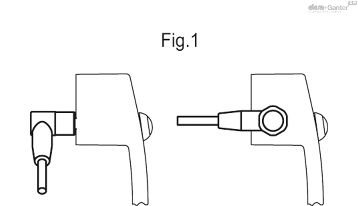
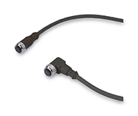
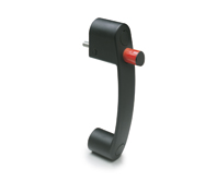
In case of use of an extension with angled connector, the direction of the cable output is shown in the Fig.1.
EBR-SWB handle can be assembled with EBR neutral handle.
Technical data
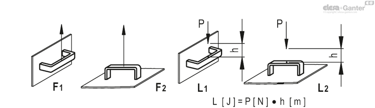
Tensile stress and impact strength: the values F1, F2, L1 and L2 indicated in the table were obtained during breaking tests carried out with the appropriate dynamometric equipment under the test conditions shown in the figure with ambient temperature.
| Electrical Features | |||
| Load | Voltage | Current | Max Cycles |
| Resistive | 12 Vdc | 4 A | 200000 |
| Resistive | 48 Vdc | 1 A | 200000 |
| Resistive | 48 Vdc | 2 A | 100000 |
| Resistive | 48 Vdc | 3 A | 75000 |
| Logic level | 5 Vdc | 10 mA | 200000 |
| DWV | 1000 Vrms | - | - |
Accessories
Accessories on request
FC-M12x1: extensions with 8 pole M12 female axial connector.
Other executions
Other standard executions
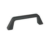
- EBR.: single complementary handle without switch.
- EBR-SWM: handle with monostable electrical switch.
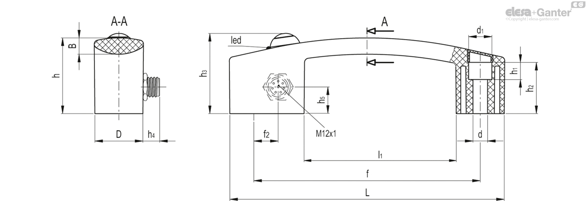
EBR-SWB-R-C
| L | f | d | d1 | f2 | D | h | h1 | h2 | h3 | h4 | h5 | B | l1 | F1 [N] |
F2 [N] |
L1 [J] |
L2 [J] |
||||
|---|---|---|---|---|---|---|---|---|---|---|---|---|---|---|---|---|---|---|---|---|---|
| Code | Description | Actions | |||||||||||||||||||
| 260591-C1 | EBR.150-SWB-R-C | 160 | 132±0.5 | 8.5 | 13.5 | 14.5 | 28 | 44 | 10 | 30 | 47 | 16 | 14 | 8.5 | 89 | 2800 | 2900 | 35 | 8 | 116 |
|

Enquiry Now
To allow us to respond to your enquiry promptly, please provide all required information.
Related Products
-
 EBR-SWMHandle with monostable electrical switchTechnopolymerView Product
 -
 GN 331Tubular HandlesTube Aluminum, Handle Legs Zinc Die Casting, with Electrical Switching FunctionView Product
 -
 GN 728Cabinet U-HandlesAluminum Die CastingView Product
 -
 GN 330Cables with Connector CouplingView Product
 -
 GN 332Tubular HandlesTube Aluminum, Handle Legs Zinc Die Casting, with Electrical Switching FunctionView Product
 -
 EBR.Bridge handlesTechnopolymerView Product
 -
 EBR-CHHandle with safety locking deviceFor retractable sliding doors, technopolymerView Product
 -
 CFSW.Hinges with built-in safety switchSUPER-technopolymerView Product
 -
 CFSQHinges with built-in safety switchSUPER-technopolymerView Product

