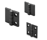
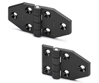
CFM-TR-G
Hinges for mounting on glass or panels
SUPER-Technopolymer
Description
Main specifications
Material
Glass-fibre reinforced polyamide based (PA) SUPER-technopolymer, black colour, matte finish.
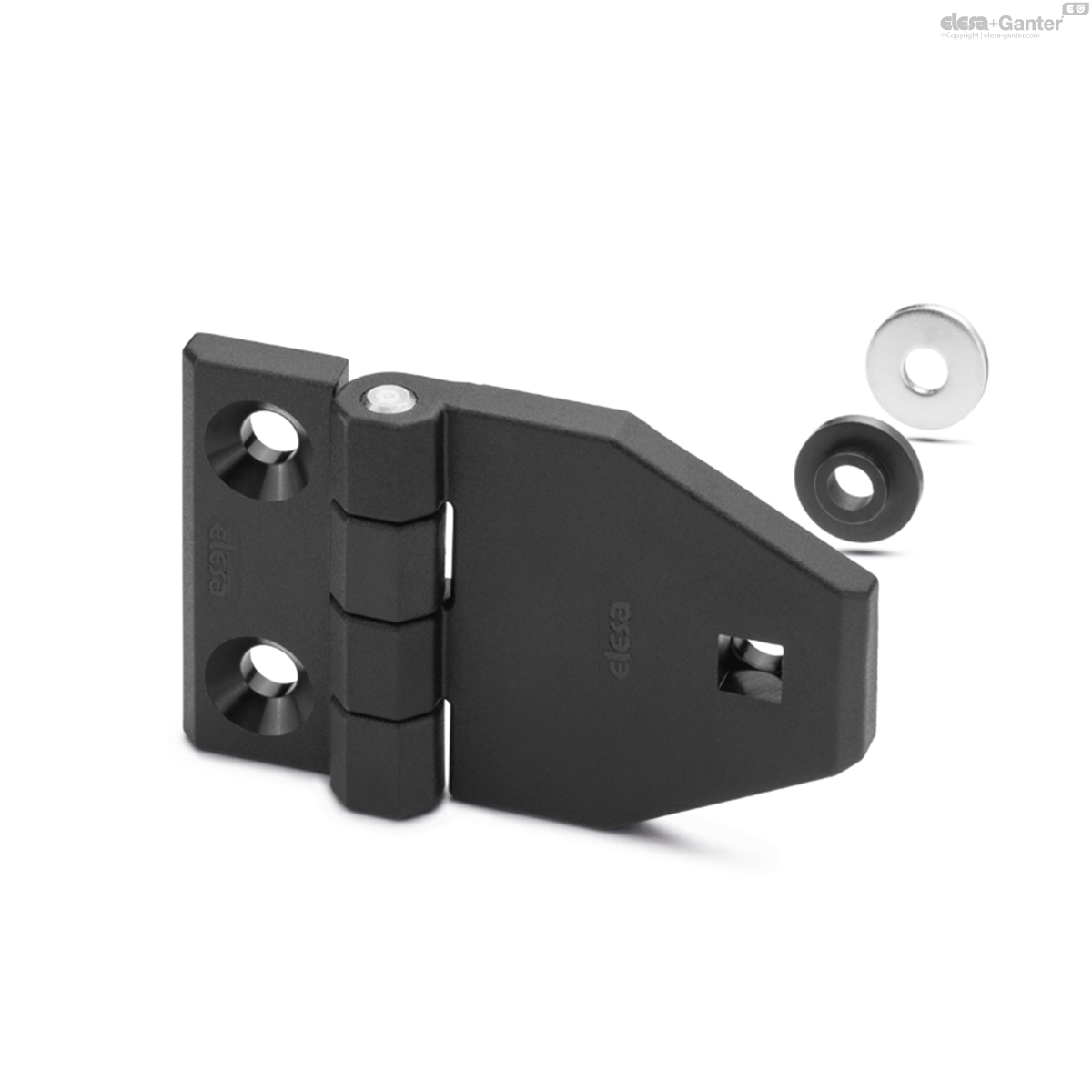
Flat washer
A4 UNI 6593-MT stainless steel.
Step washer
NBR rubber, hardness 70 Shore A.
Produced from FDA compliant raw material (FDA CFR.21 and EU 10/2011).
Rotating pin
AISI 303 stainless steel.
Standard execution
Frame side: pass-through holes for countersunk head screws.
Panel side: pass-through hole for round head square neck bolts according to UNI 5732 (choose the correct screw length depending on the thickness of the glass or of the panel).
General information
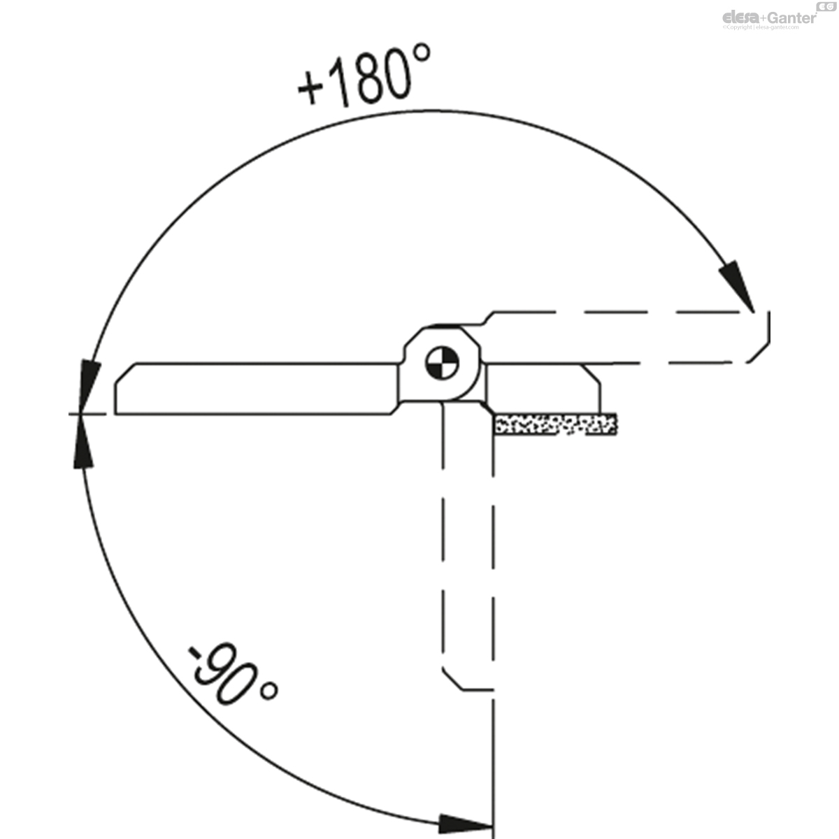
Rotation angle (approximate value)
Max 270° (-90° and +180° being 0° the condition where the two interconnected surfaces are on the same plane).
Do not exceed the rotation angle limit so as not to prejudice the hinge mechanical performance.
To choose the convenient type and the right number of hinges for your application, see the Guidelines.

| Resistance tests | AXIAL STRESS | RADIAL STRESS | Load at breakage R90 [N] | |||
| Description | Maximum working load Ea [N] | Load at breakage Ra [N] | Maximum working load Er [N] | Load at breakage Rr [N] | Maximum working load E90 [N] | Load at breakage R90 [N] |
| CFM-TR-G-B.40-SH-5 | 300 | 750 | 420 | 2500 | 420 | 1000 |
| CFM-TR-G-B.50-SH-6 | 270 | 1040 | 480 | 3500 | 480 | 1000 |
| CFM-TR-G-B.60-SH-6 | 250 | 1200 | 370 | 5000 | 370 | 2500 |
The maximum operating load values of the different hinges shown in the tables are merely indicative. They are the result of tests carried out in our laboratories at controlled temperature and humidity (23°C - 50% RH), under specific conditions of use and for a limited period of time. In any case, it is advisable to verify correct operation during installation of the structure.
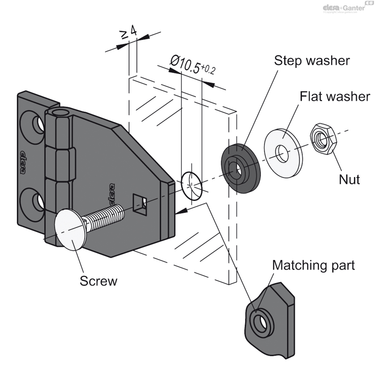
Instructions of use
Assembly instructions on glass or panels
- Drill a hole Ø 10.5 +0.2 in the glass or in the panel (min. thickness 4 mm).
- Place the hinge frontally centring the matching part (d3) in the hole and insert the screw.
- On the opposite side, insert the step washer, flat washer and tighten with a nut (Fig.1).
At least two hinges need to be mounted for correct operation.

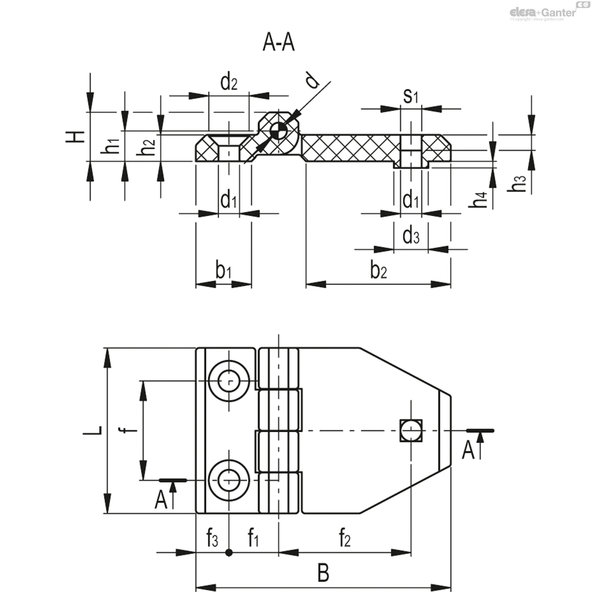
| L | B | f | f1 | f2 | f3 | H | h1 | h2 | h3 | h4 | b1 | b2 | d | d1 | d2 | d3 | s1 | C# [Nm] |
||||
|---|---|---|---|---|---|---|---|---|---|---|---|---|---|---|---|---|---|---|---|---|---|---|
| Code | Description | Actions | ||||||||||||||||||||
| 426051 | CFM-TR-G-B.40-SH-5 | 40 | 64 | 25 | 12.5 | 32.5 | 7.5 | 9 | 5.5 | 5 | 4.1 | 2 | 14 | 38.5 | 4 | 5.5 | 10.5 | 10.5 | 5.6 | 3 | 29 |
|
| 426061 | CFM-TR-G-B.50-SH-6 | 50 | 77 | 30 | 15 | 39.5 | 10.5 | 11.5 | 6.5 | 6 | 4.7 | 2 | 18 | 45 | 6 | 6.5 | 12.5 | 10.5 | 6.6 | 5 | 46 |
|
| 426071 | CFM-TR-G-B.60-SH-6 | 60 | 90 | 36 | 18 | 47.5 | 12.5 | 15 | 8.5 | 8 | 4.7 | 2 | 21 | 51.5 | 8 | 6.5 | 12.5 | 10.5 | 6.6 | 5 | 83 |
|

Enquiry Now
To allow us to respond to your enquiry promptly, please provide all required information.