

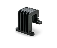
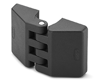
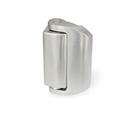
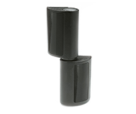
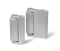
CFD.
Hinges for narrow jamb
Technopolymer

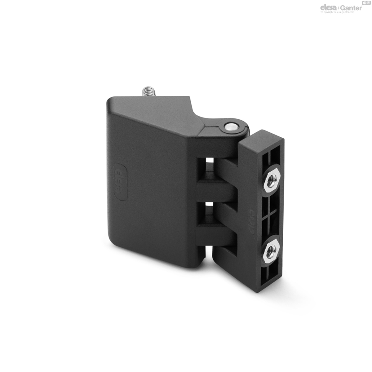
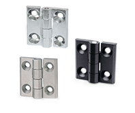
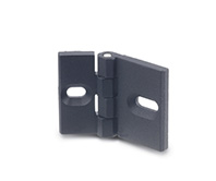
CFD-B
Hinges for narrow jamb
Bosses with threaded hole
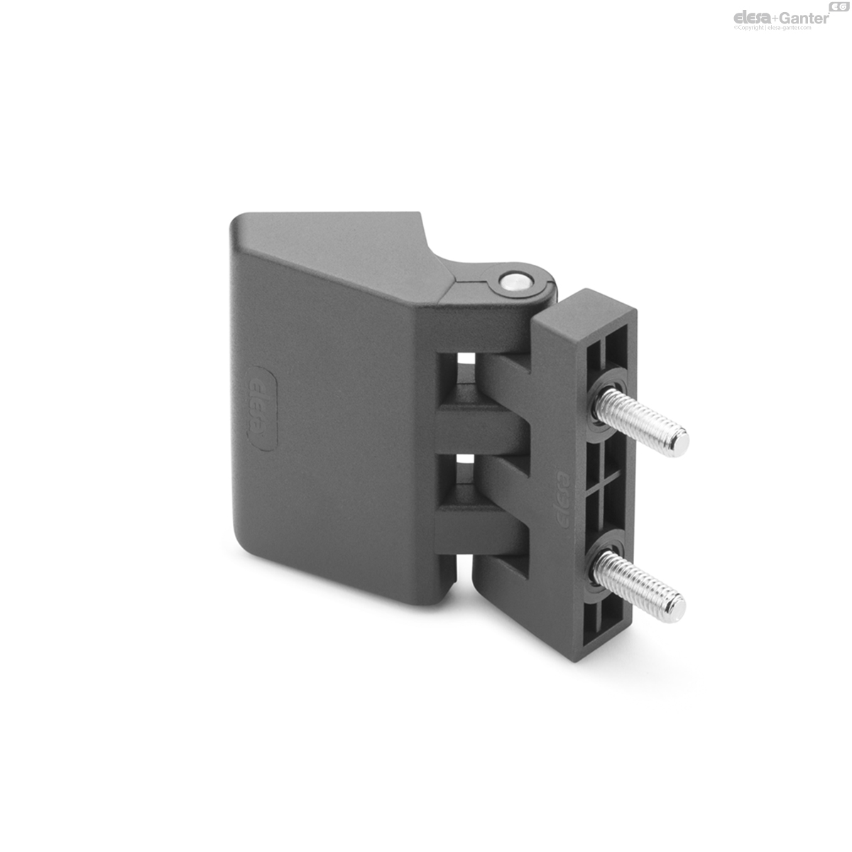
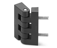
CFD-p
Hinges for narrow jamb
Threaded studs
CFD-p-B
Hinges for narrow jamb
Threaded studs and bosses with threaded hole

CFD-B-p
Hinges for narrow jamb
Bosses with threaded hole and threaded studs
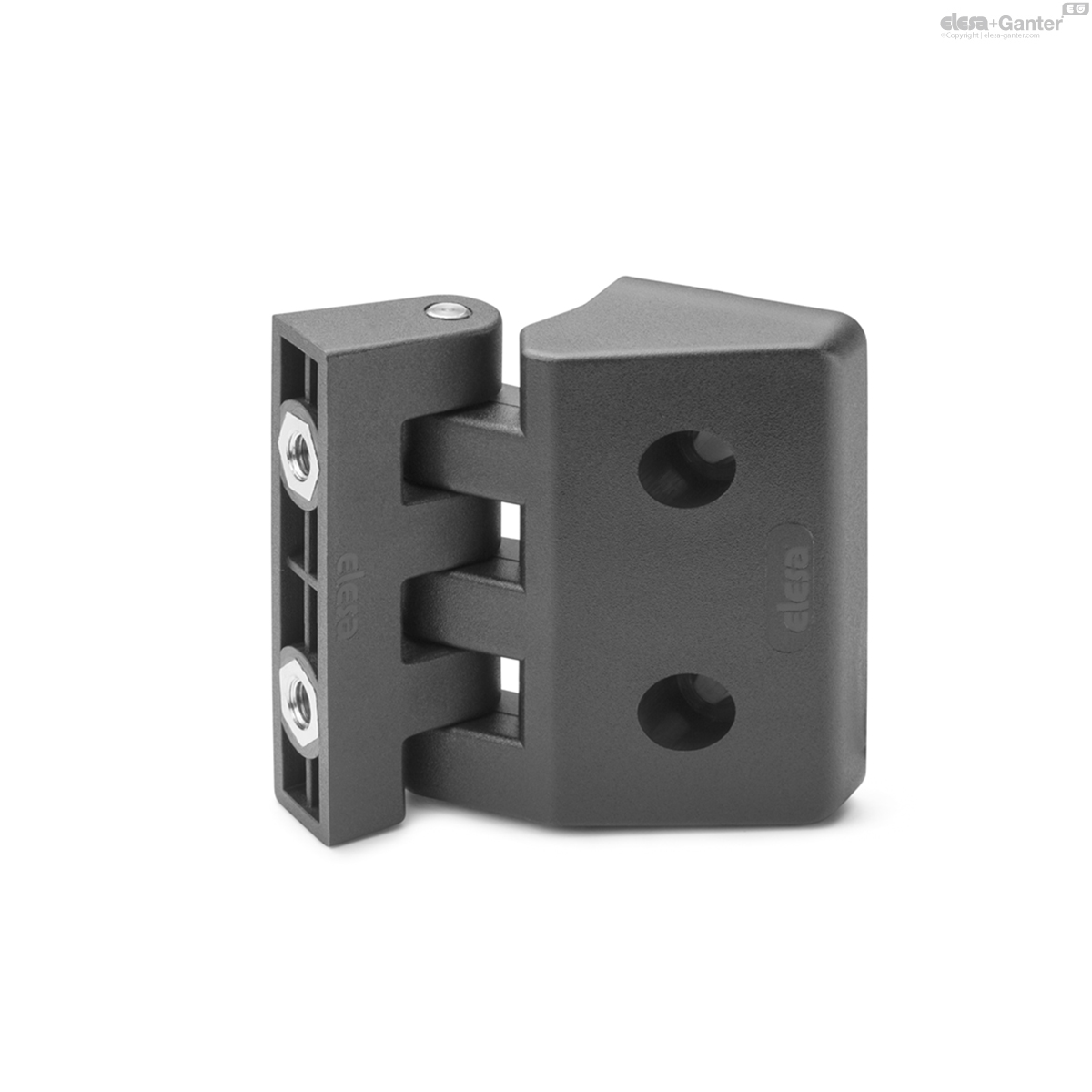
CFD-CH-B
Hinges for narrow jamb
Pass-through holes for cylindrical head screws and bosses with threaded hole
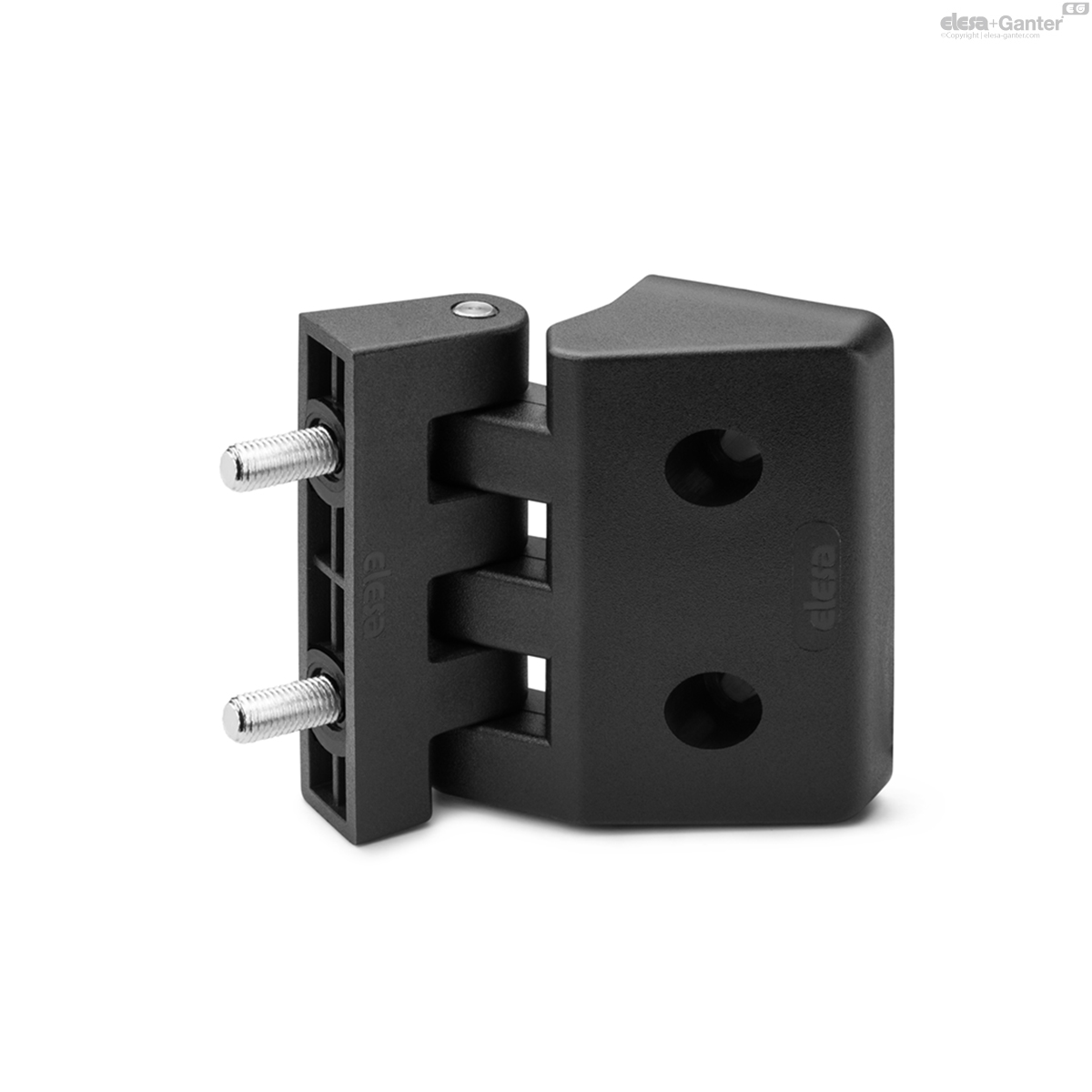
CFD-CH-p
Hinges for narrow jamb
Pass-through holes for cylindrical head screws and threaded studs


Description
Main specifications
Material
High-resilience polyamide based (PA) technopolymer, black colour, matte finish.
Rotating pin
AISI 303 stainless steel.
Standard executions
- CFD-B: nickel-plated brass bosses with threaded hole.
- CFD-p: nickel-plated brass threaded studs in the wide body, nickel-plated steel threaded studs in the narrow body.
- CFD-p-B: nickel-plated brass threaded studs and nickel-plated brass bosses with threaded hole.
- CFD-B-p: nickel-plated brass bosses with threaded hole and nickel-plated steel threaded studs.
- CFD-CH-B: pass-through holes for cylindrical head screws and nickel-plated brass bosses with threaded hole.
- CFD-CH-p: pass-through holes for cylindrical head screws and nickel-plated steel threaded studs.
General information
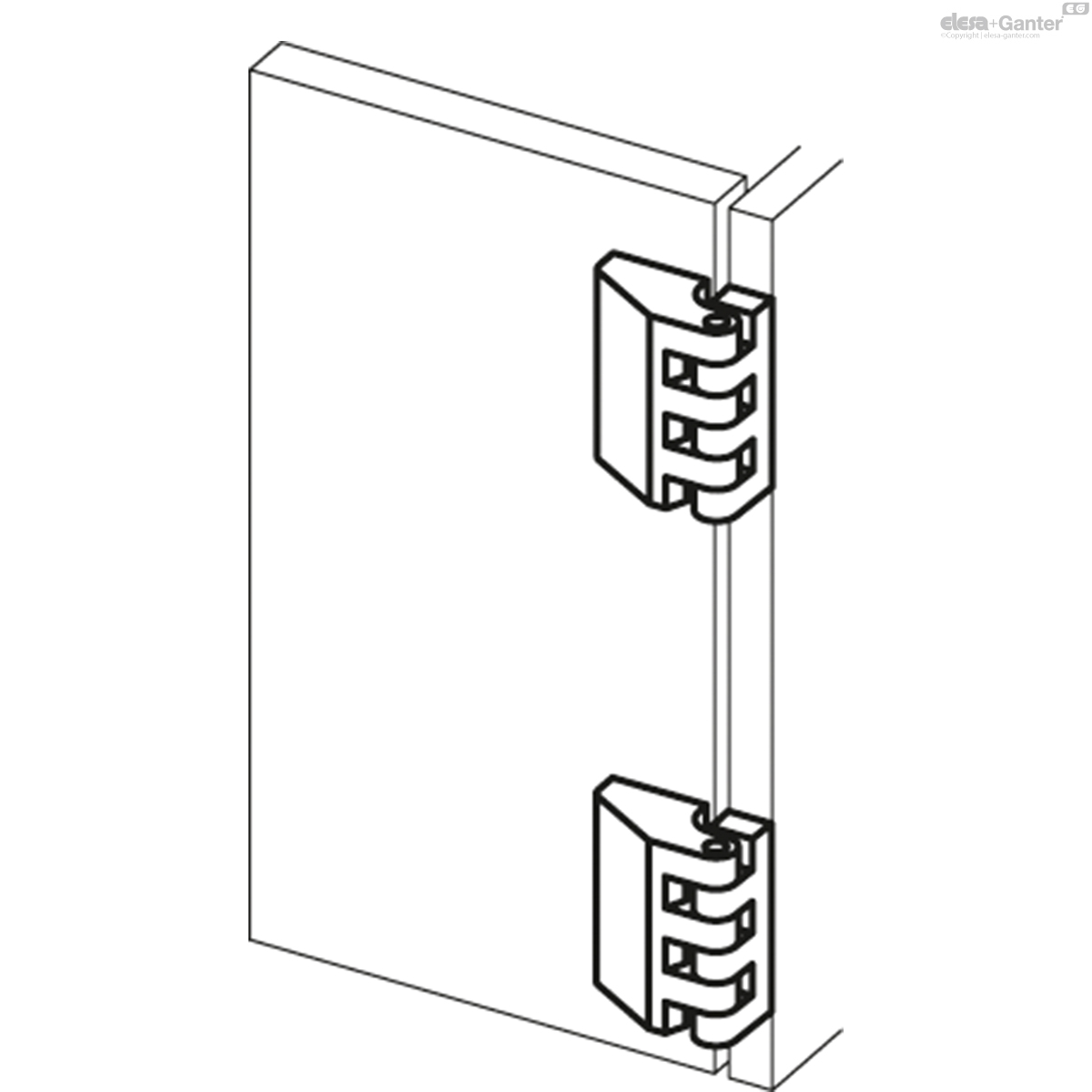
Features and applications
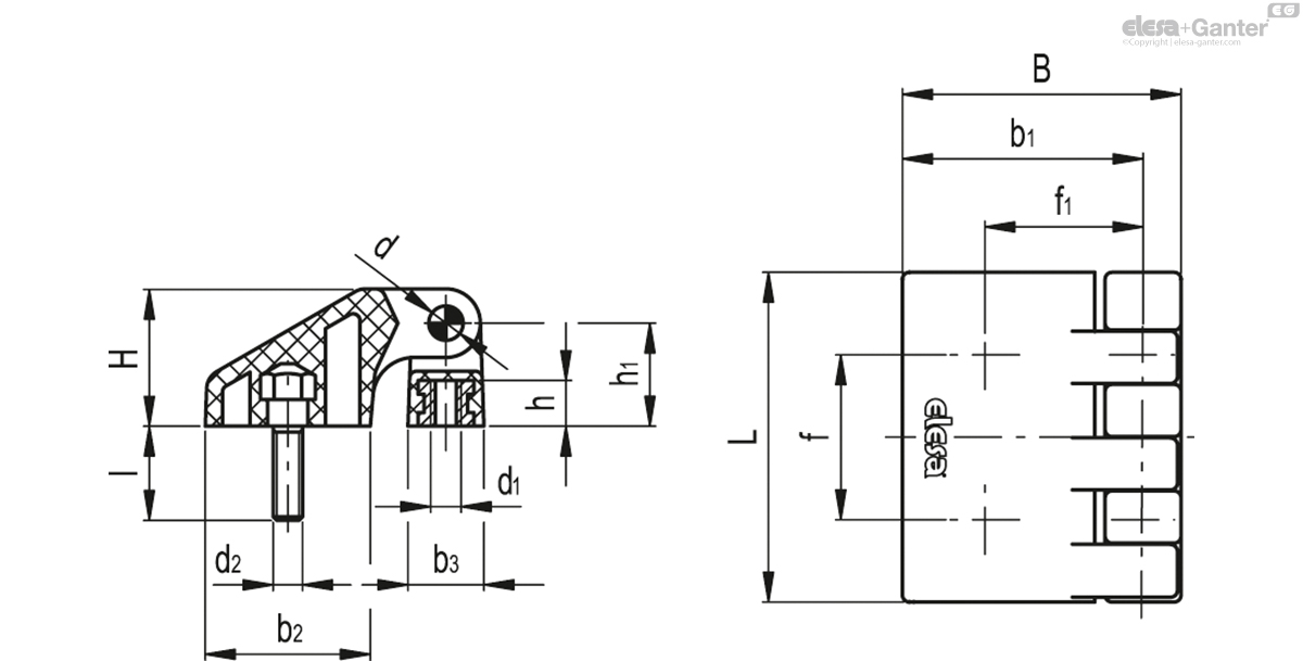
The hinge is made up of two bodies with different dimensions (a narrow one and a larger one) and can be assembled for example on structures with thin frame or door.
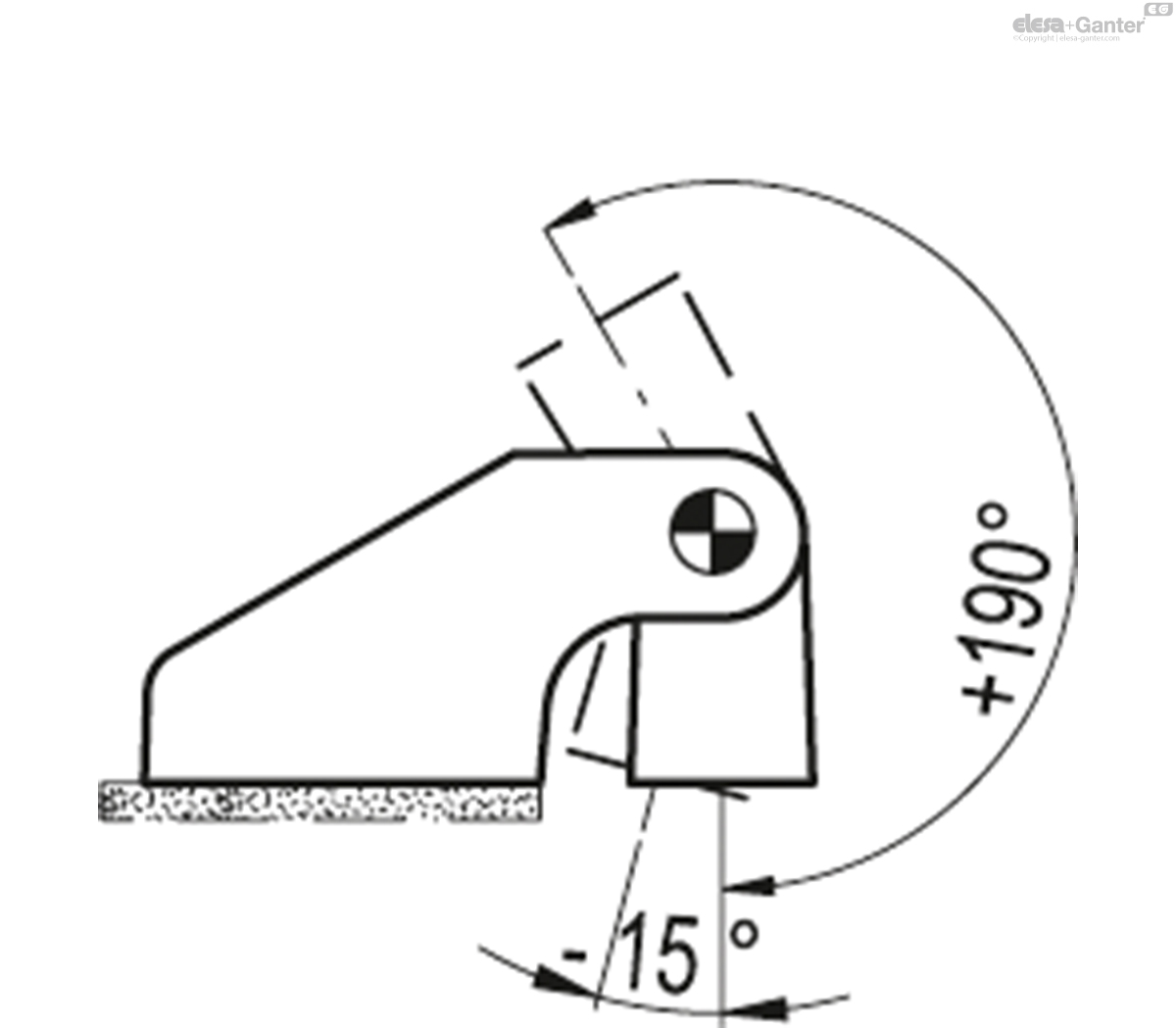
Rotation angle (approximate value)
Max 205° (-15° and +190° being 0° the condition where the two interconnected surfaces are on the same plane).
Do not exceed the rotation angle limit so as not to prejudice the hinge mechanical performance.
To choose the convenient type and the right number of hinges for your application, see the Guidelines-.
| Resistance tests | AXIAL STRESS | RADIAL STRESS | 90° ANGLED STRESS | |||
| Description | Maximum working load Ea [N] | Load at breakage Ra [N] | Maximum working load Er [N] | Load at breakage Rr [N] | Maximum working load E90 [N] | Load at breakage R90 [N] |
| CFD.30 B-M3 | 60 | 690 | 70 | 490 | 60 | 500 |
| CFD.30 p-M3x13 | 70 | 750 | 40 | 340 | 30 | 390 |
| CFD.30 p-M3x13-B-M3 | 60 | 690 | 40 | 340 | 30 | 390 |
| CFD.30 B-M3-p-M3x13 | 60 | 690 | 40 | 340 | 30 | 390 |
| CFD.30 CH-3-B-M3 | 100 | 830 | 110 | 720 | 70 | 670 |
| CFD.30 CH-3-p-M3x13 | 60 | 730 | 50 | 450 | 30 | 350 |
| CFD.40 B-M4 | 160 | 1710 | 150 | 1340 | 100 | 700 |
| CFD.40 p-M4x18 | 110 | 1230 | 140 | 880 | 50 | 730 |
| CFD.40 p-M4x18-B-M4 | 110 | 1230 | 140 | 880 | 50 | 700 |
| CFD.40 B-M4-p-M4x18 | 110 | 1230 | 140 | 880 | 50 | 700 |
| CFD.40 CH-4-B-M4 | 120 | 1620 | 150 | 1220 | 130 | 1110 |
| CFD.40 CH-4-p-M4x18 | 150 | 1480 | 140 | 820 | 100 | 860 |
| CFD.48 B-M5 | 260 | 2440 | 260 | 1700 | 120 | 1640 |
| CFD.48 p-M5x17 | 290 | 1770 | 240 | 1840 | 110 | 1740 |
| CFD.48 p-M5x17-B-M5 | 260 | 1770 | 240 | 1700 | 110 | 1640 |
| CFD.48 B-M5-p-M5x17 | 260 | 1770 | 240 | 1700 | 110 | 1640 |
| CFD.48 CH-5-B-M5 | 330 | 2530 | 240 | 1890 | 290 | 1870 |
| CFD.48 CH-5-p-M5x17 | 150 | 2170 | 120 | 1200 | 110 | 970 |
| CFD.66 B-M6 | 450 | 4130 | 320 | 2520 | 220 | 2250 |
| CFD.66 p-M6x16 | 470 | 3260 | 260 | 1700 | 240 | 1580 |
| CFD.66 p-M6x16-B-M6 | 450 | 3260 | 260 | 1700 | 220 | 1580 |
| CFD.66 B-M6-p-M6x16 | 450 | 3260 | 260 | 1700 | 220 | 1580 |
| CFD.66 CH-6-B-M6 | 430 | 3660 | 410 | 2610 | 310 | 2830 |
| CFD.66 CH-6-p-M6x16 | 350 | 3090 | 280 | 1770 | 180 | 1610 |
CFD-p-B
| L | B | d1 | h | d2 | l | f±0.25 | f1 ±0.25 | H | h1 | b1 | b2 | b3 | d | C [Nm] B# |
C [Nm] p# |
||||
|---|---|---|---|---|---|---|---|---|---|---|---|---|---|---|---|---|---|---|---|
| Code | Description | Actions | |||||||||||||||||
| 422731 | CFD.30 p-M3x13-B-M3 | 30.5 | 26.5 | M3 | 4 | M3 | 13 | 15 | 15 | 12.5 | 9.5 | 22.5 | 15 | 7 | 2.5 | 1 | 1 | 10 |
|
| 422831 | CFD.40 p-M4x18-B-M4 | 40.5 | 34 | M4 | 5.5 | M4 | 18 | 20 | 20.2 | 16.5 | 12.5 | 29.5 | 20 | 9.5 | 4 | 4 | 1.5 | 23 |
|
| 422931 | CFD.48 p-M5x17-B-M5 | 48.5 | 40.5 | M5 | 6.5 | M5 | 17 | 24 | 23 | 20 | 15 | 35 | 24 | 11.5 | 5 | 5 | 3 | 41 |
|
| 423031 | CFD.66 p-M6x16-B-M6 | 66 | 56 | M6 | 9 | M6 | 16 | 33 | 31.8 | 27.5 | 21 | 48.5 | 33 | 15 | 6 | 5 | 5 | 90 |
|

Enquiry Now
To allow us to respond to your enquiry promptly, please provide all required information.
Related Products
-
 CHG.Concealed hingeSUPER-technopolymerView Product
 -
 CFE.HingesTechnopolymerView Product
 -
 GN 237HingesZinc die casting / Stainless Steel / AluminumView Product
 -
 GN 139.6Hinges without safety switchStainless SteelView Product
 -
 CFO.Offset lift-off hingeTechnopolymerView Product
 -
 GN 139.2Hinges without safety switchZinc die castingView Product
 -
 GN 161HingesAccessory for profile systems / Zinc die castingView Product
 -
 CFF.Hinges for narrow jambs and doorsTechnopolymerView Product

