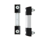
SLCK
Kit for the electric control of a fluid level
for HCK. oil level indicators
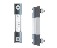
SLCK
Kit for the electric control of a fluid level
With DIN 43650C male connector, for applications with temperatures up to 80°C
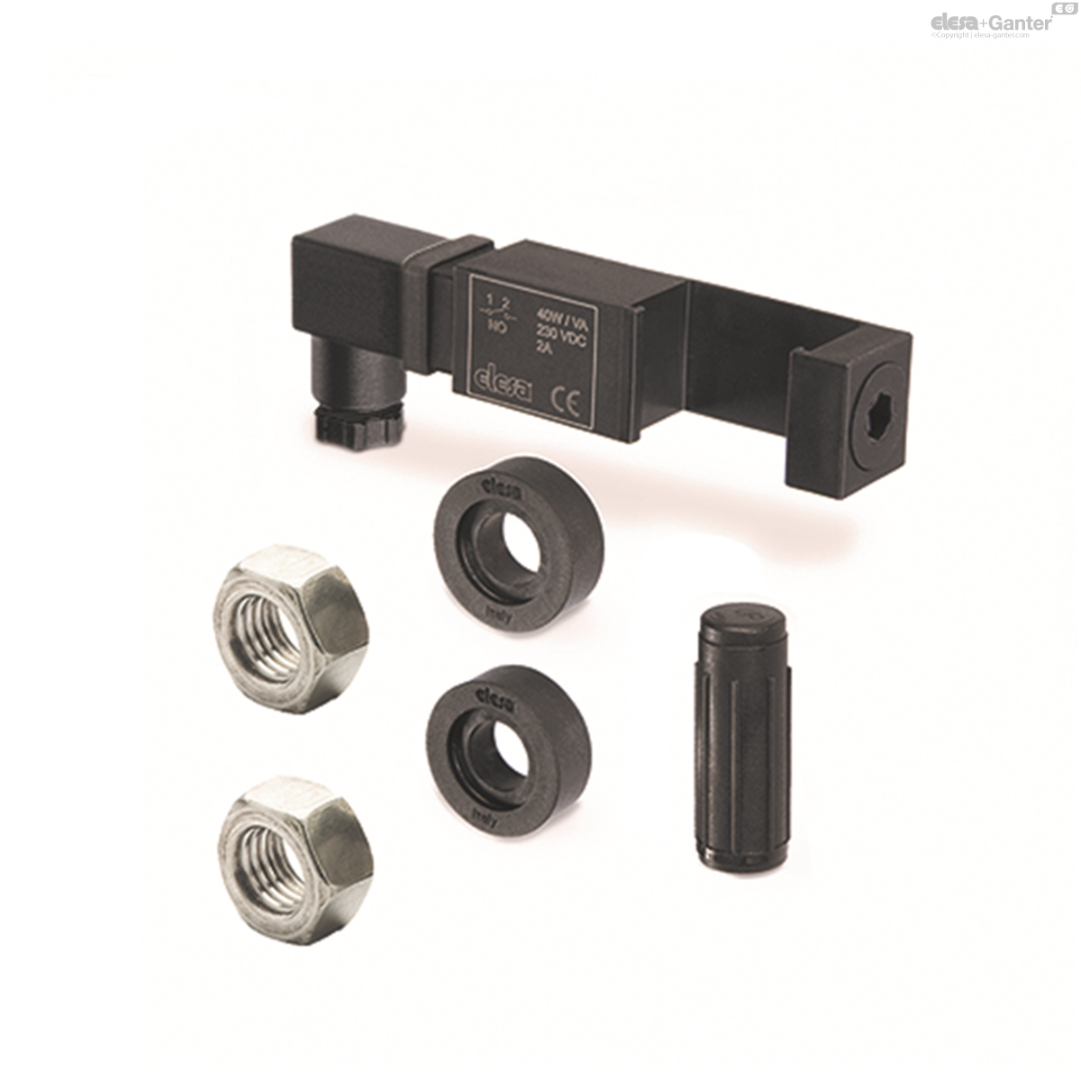
SLCK-HT
Kit for the electric control of a fluid level
With DIN 43650C male connector, for applications with temperatures up to 120°C
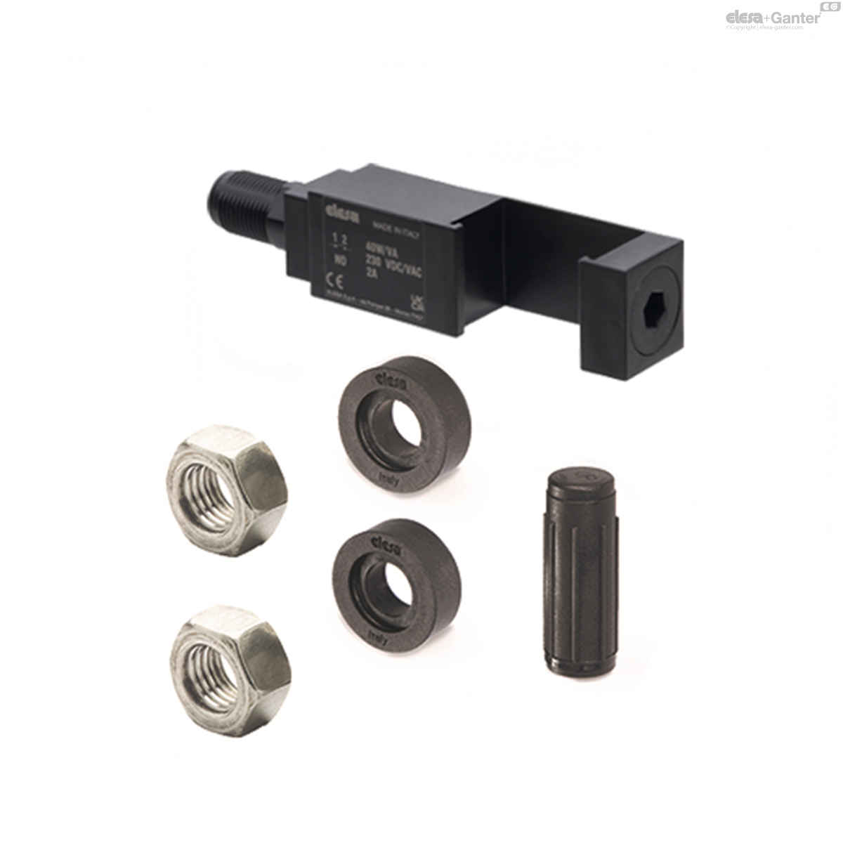
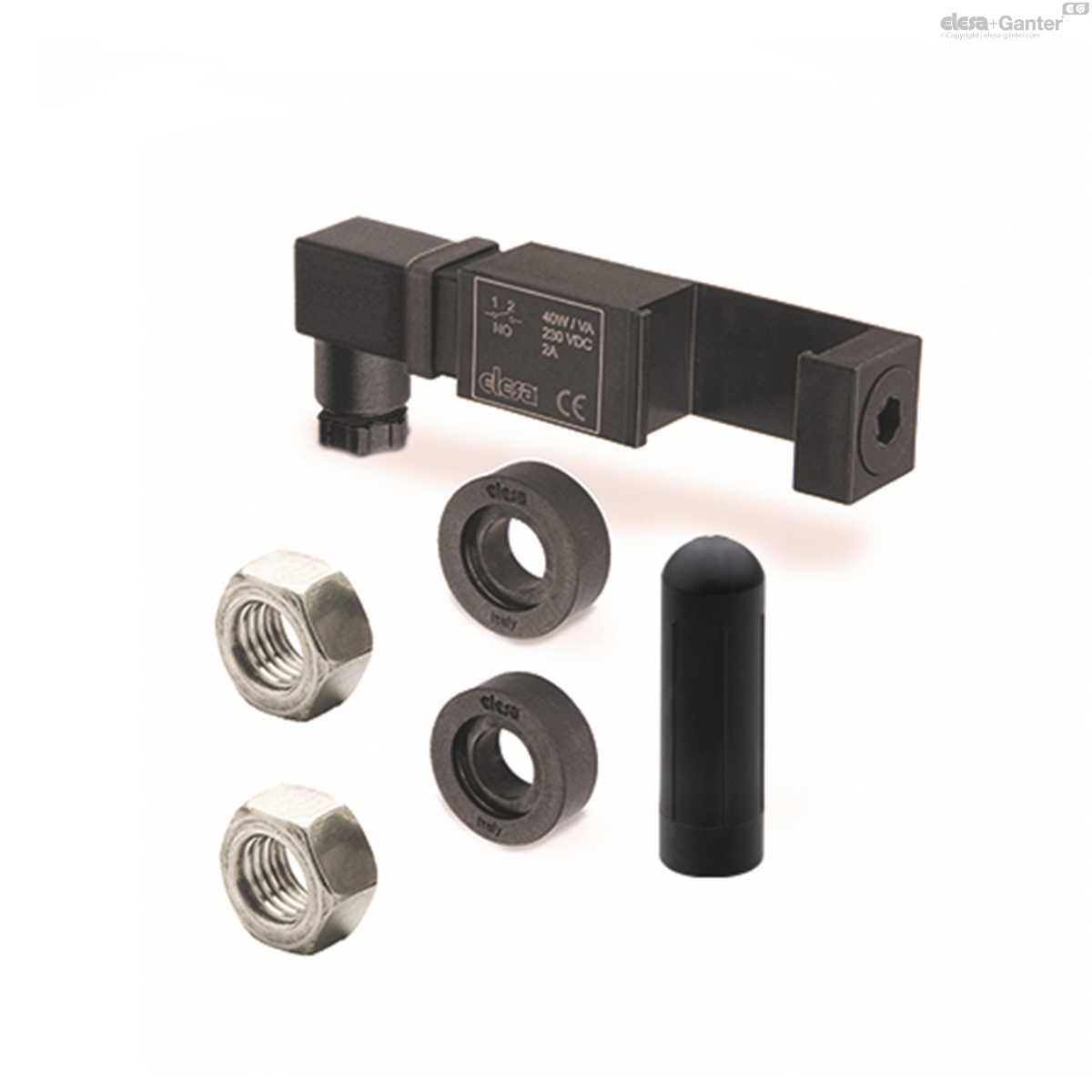
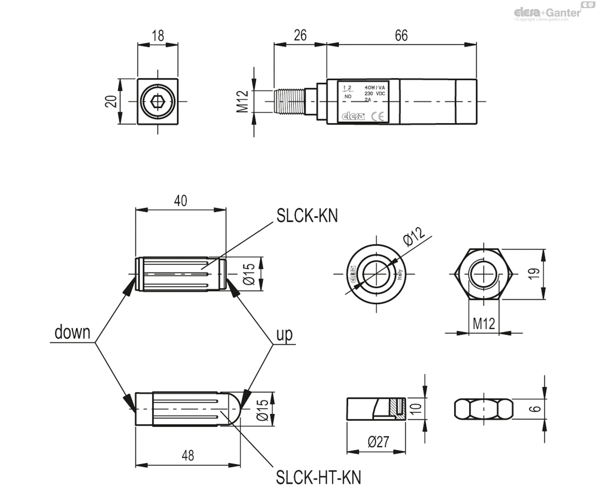
SLCK-KN
Kit for the electric control of a fluid level
With M12 male connector, for applications with temperatures up to 80°C
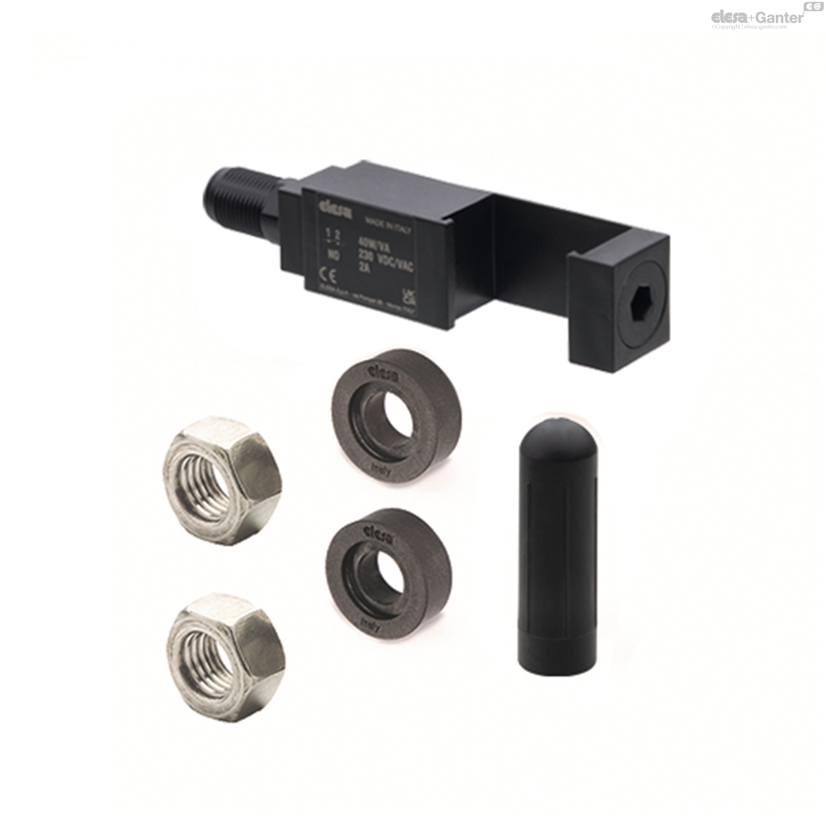
SLCK-HT-KN
Kit for the electric control of a fluid level
With M12 male connector, for applications with temperatures up to 120°C


Description
Main specifications
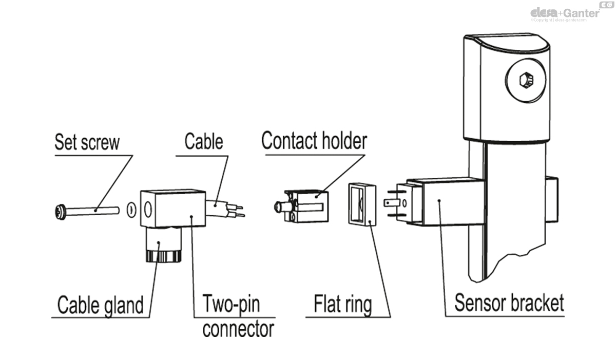
Sensor holder bracket
In black polyamide based (PA) technopolymer, watertight, incorporating the relay (reed) with two conductors wired to the connector.
It can be moved along the axis of the indicator and secured in the preferred position with the appropriate screw (set screw) in technopolymer.
Electric sensor
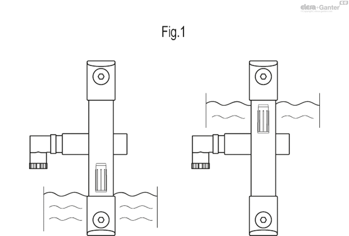
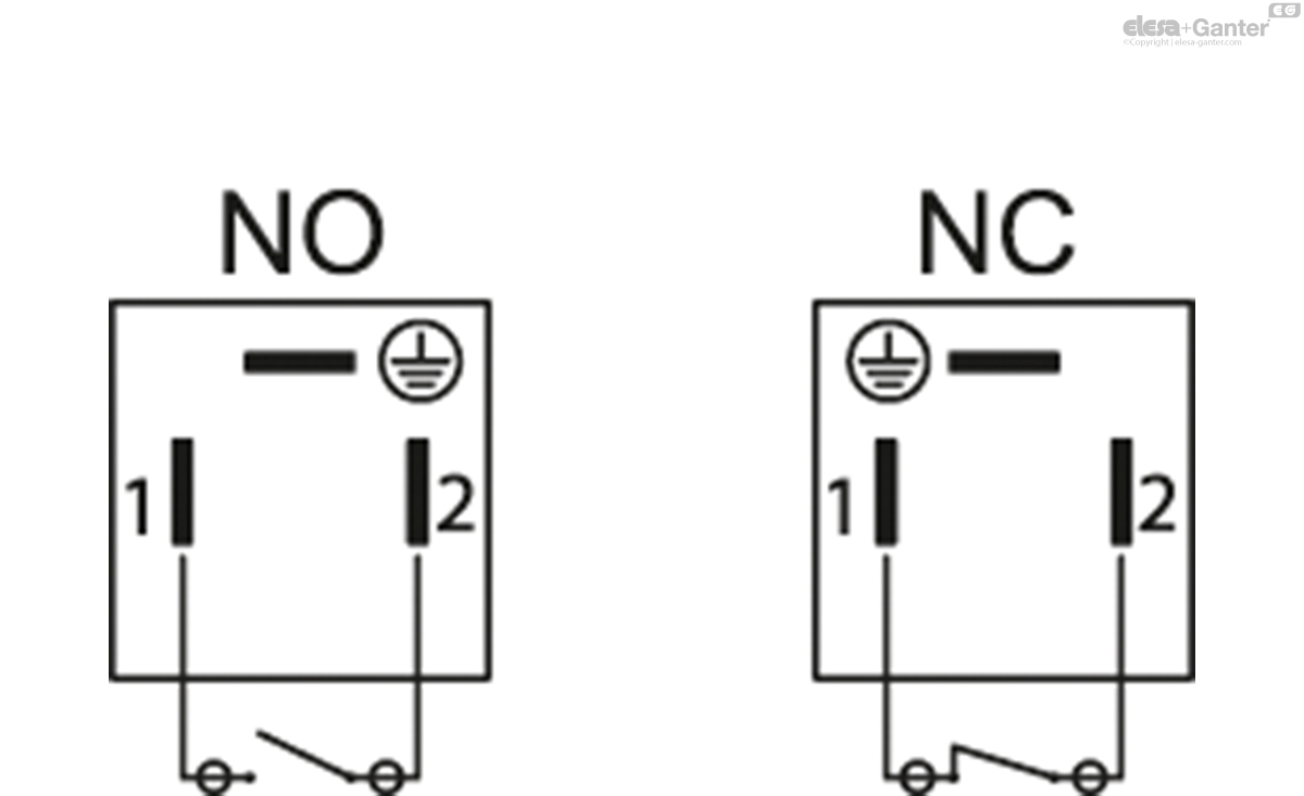
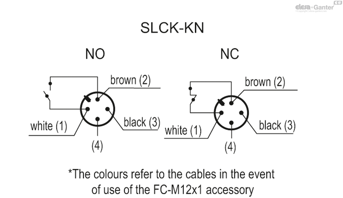
With NO and NC (initial status of the reed sensors) we mean the condition of the electrical contact when the tank is full and therefore the float is in the upper position (Fig.1).
- NC: the electrical circuit closes when the float crosses the sensor during the tank filling phase. In the same way, the electrical circuit opens when the float passes through it during the emptying phase of the tank.
- NO: the electrical circuit opens when the float crosses the sensor during the tank filling phase. In the same way, the electrical circuit closes when the float passes through it during the emptying phase of the tank.
Float
Polypropylene based (PP) technopolymer, max temperature limit 80° C or polyamide based (PA) technopolymer, max temperature limit 120°C, max chemical compatibility, black colour.
The float incorporates a magnetic element to activate the electric contact. When the float reaches the intervention level set by the user, by suitably positioning the sensor holder along the axis of the indicator, the electrical contact activates.
Max operating pressure 2 bar (operation with oil)
Spacer sleeves
In polyamide based (PA) technopolymer. Essential in cases where the reservoir is made out of ferromagnetic material in order to prevent the interaction between the magnet and the metal mass of the reservoir.
Male connector
- DIN 43650 C connector in glass-fibre reinforced polyamide based (PA) technopolymer, black colour.
- 4-pole M12x1 connector, with threading in glass-fibre reinforced polyamide based (PA) technopolymer certified self-extinguishing UL-94-V0, black colour, matte finish.
For a correct assembly see Warnings.
Female connector (DIN 43650 C)
With built-in cable gland and contact holder. Front or axial output (high or low) ensuring protection against water sprays (protection class IP 65 according to table EN 60529) can be increased during installation with the appropriate precautions.
NBR synthetic rubber packing ring.
Kit
The kit includes one or two sensor holder brackets, a float, 4 O-rings (2 FKM for HCK-GL and 2 NBR for HCK), two spacers and two M12 UNI 5589 AISI 316 stainless steel nuts.
It is possible to apply more than one kit to get the electric control of different levels, consistently with the height of the transparent column.
Standard executions
For applications with temperatures up to 80°C: polypropylene based (PP) technopolymer float.
- SLCK-NO: with electric contact normally open.
- SLCK-NC: with electric contact normally closed.
- SLCK-NO-NC: with one electric contact normally open and one electric contact normally closed.
- SLCK-NC-NC: with two electric contacts normally closed.
- SLCK-NO-NO: with two electric contacts normally open.
For applications with temperatures up to 120°C: polyamide based (PA) technopolymer float.
- SLCK-HT-NO: with electric contact normally open.
- SLCK-HT-NC: with electric contact normally closed.
- SLCK-HT-NO-NC: with one electric contact normally open and one electric contact normally closed.
- SLCK-HT-NC-NC: with two electric contacts normally closed.
- SLCK-HT-NO-NO: with two electric contacts normally open.
- KN: suffix to be added for versions with M12 male connector
| Electric sensor | Contact status | |
|---|---|---|
| Tank full | Tank empty | |
| SLCK-NO | NO | NC |
| SLCK-NC | NC | NO |
Accessories on request
Accessories on request
FC-M12x1 extensions with 4 pole M12 female axial connector.
General information
Features and performances
With the application of the SLCK kit, HCK. and HCK-GL column level indicators provide an electric signal when the fluid level reaches the level of preset intervention, besides the visual control of the level. The electric control of the level can be applied on all versions of HCK. from the version with 127 mm hole centre distance while always maintaining the visibility of fluid level even from side positions.
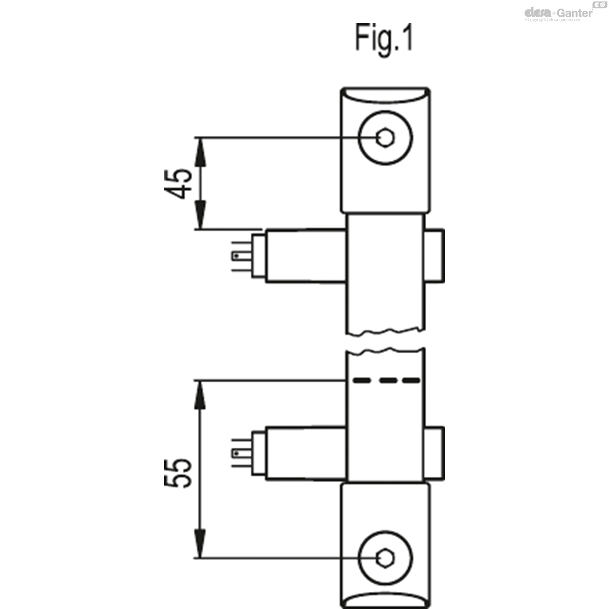
In the highest position, for switching to occur correctly, the sensor holder must be positioned at least 45 mm below the axis of the high screw (Fig.2).
In the lowest position, the level of the fluid which determines the switching of the electrical circuit is approximately 55 mm above the axis of the low fluid supply screw (data refers to mineral oil type CB68, according to ISO 3498, temperature 23°C) (Fig.2).
The sensor holder is arranged to be installed to the left with respect to the axis of the indicator. However, if required it can also be mounted on the right. The connector can be rotated by 90° in four positions when wiring.
For a correct assembly see Warnings.
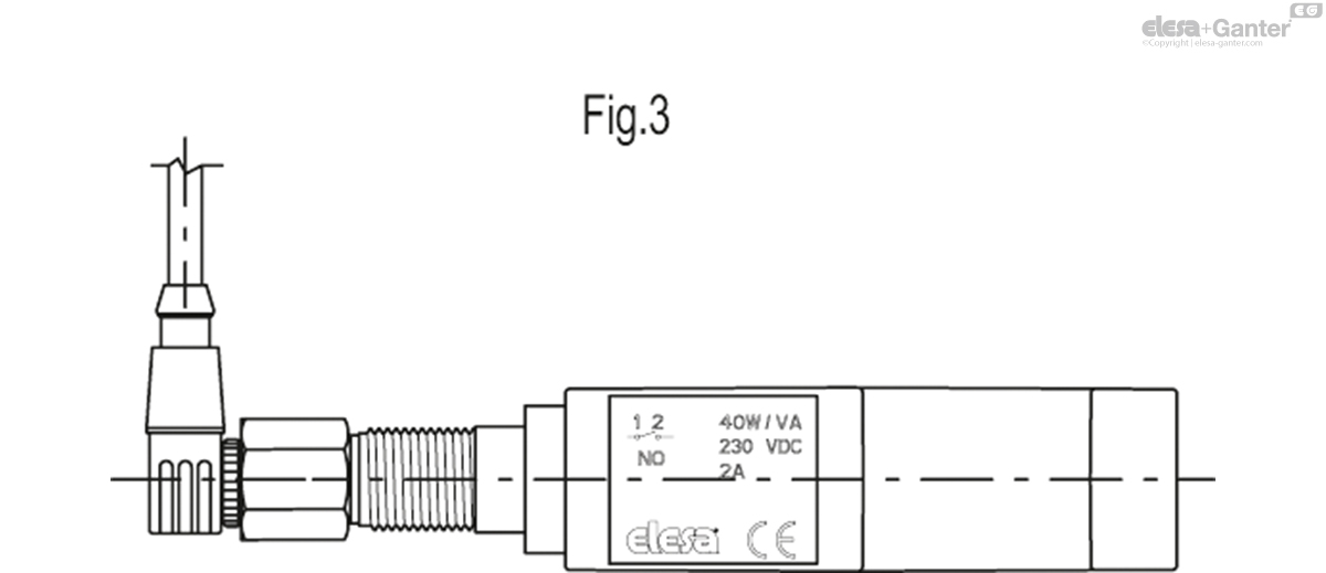
In case of use of an extension with angled connector, the direction of the cable output is shown in Fig.3.
Instructions of use
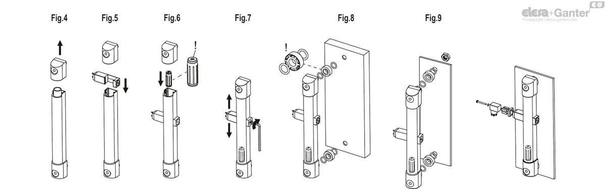
Kit assembly instructions
- Remove the indicator fixing terminal (Fig.4).
- Insert the sensor holder bracket (Fig.5).
- Insert the float with the word 'up' or the spherical end facing upwards and reallocate the fixing terminal in position (Fig.6). The float must pass through the position of the sensors for correct initialisation.
- Lock the bracket in the desired position with the grub screw (Fig.7).
- Install the indicator on the tank using the spacers included in the supply (necessary if it is a tank made of ferromagnetic material to avoid interactions between the magnet and the metal mass) (Fig.8).
- If the walls of the tank are thin and therefore it is not possible to have threaded holes, use the nuts supplied (max door thickness = 2mm) (Fig.9).
- Mount the bipolar connector after having wired it (output DIN 43650 C) (Fig.10).

Two-pin connector assembly instructions
- Remove the connector from the sensor holder bracket by unscrewing the axial set screw, take off the contact holder and unscrew the cable gland as required.
- Slip on the cable into the connector and connect the wires to the terminals of the contact holder.
- Assemble by pressing the contact holder into the connector (the contact holder can be rotated by 90° in four positions to have a different orientation of the connector).
- Screw again the connector to the sensor holder by means of the axial set screw and then tighten the cable gland.
| Level sensor electric characteristics | |
|---|---|
| Power supply | AC/DC |
| Electric contacts | NO normally open |
| NC normally closed | |
| Maximum applicable voltage | DIN 230 Vdc / Vac |
| KN max 30 Vdc / Vac | |
| Voltage range (Type KN) | <30 Vac, <30 Vdc |
| Maximum current (CC CA) | 2 A |
| Maximum commutable power | 40 W / VA |
| Cable gland (Execution with DIN connector) | Pg 7 (for cables in sheath with Ø 6 or 7 mm) |
| Conductors cross-section (Execution with DIN connector) | Max. 1.5 mm2 |
| Do not mount this indicator in proximity to magnetic fields. | |
SLCK-HT-KN
| Code | Description | Actions | |
|---|---|---|---|
| 110082-R-KN | SLCK-HT-NO-KN | 84 |
|
| 110084-R-KN | SLCK-HT-NC-KN | 86 |
|
| 110086-R-KN | SLCK-HT-NO-NC-KN | 86 |
|
| 110088-R-KN | SLCK-HT-NC-NC-KN | 86 |
|
| 110090-R-KN | SLCK-HT-NO-NO-KN | 86 |
|

Enquiry Now
To allow us to respond to your enquiry promptly, please provide all required information.