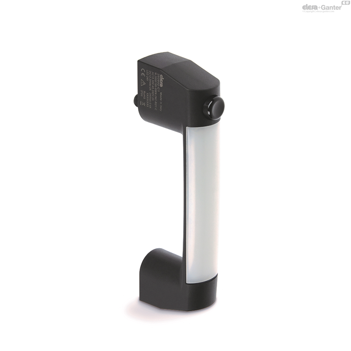
M.2000-SWM
Handles with monostable switch and LED indicator light
Self-extinguishing technopolymer
M.2000-1NC-1NO-SWM-C
Handles with monostable switch and LED indicator light
With connector, 1 NC contact + 1 NO contact
M.2000-2NC-SWM-C
Handles with monostable switch and LED indicator light
With connector, 2 NC contacts
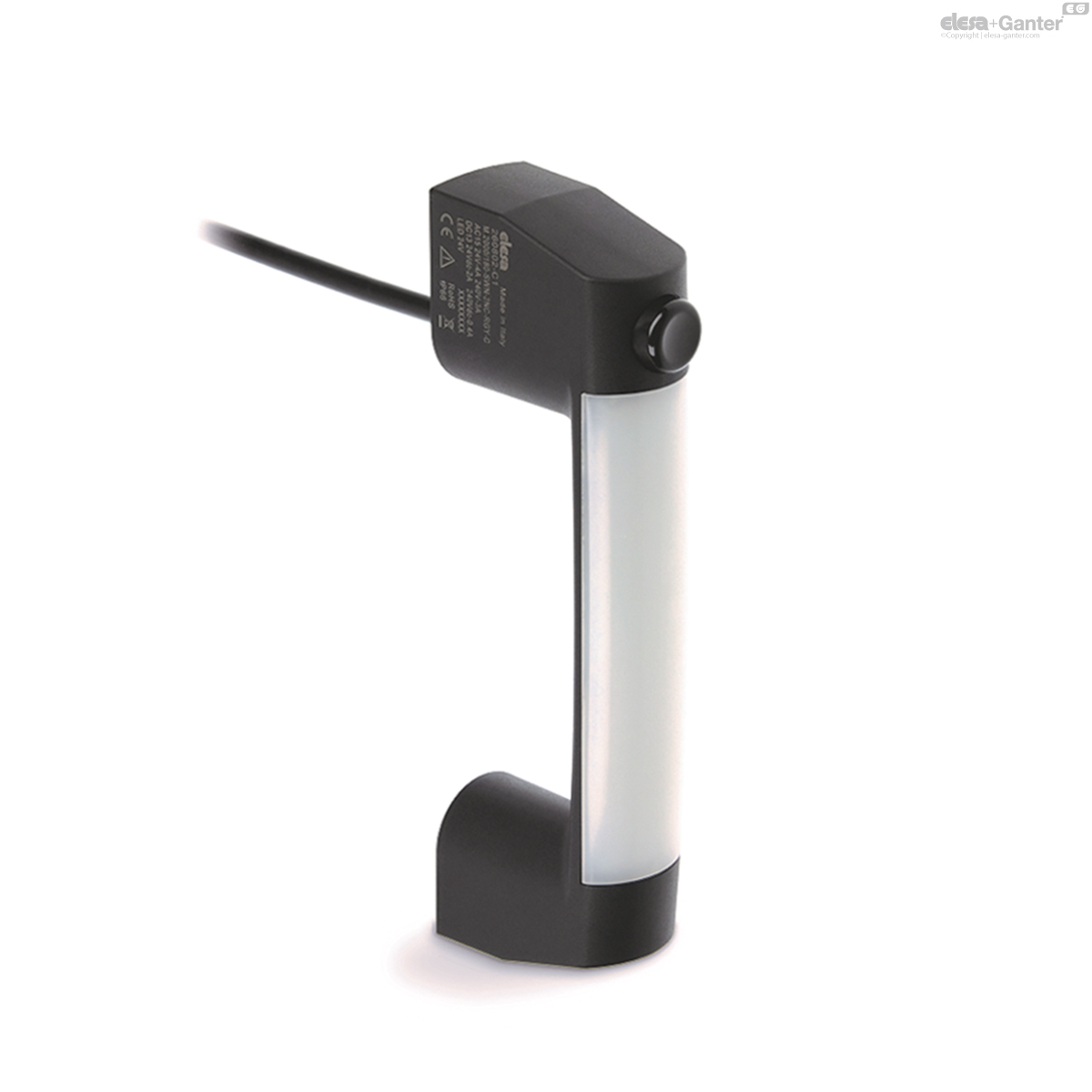
M.2000-1NC-1NO-SWM-F2.5
Handles with monostable switch and LED indicator light
With cable length 2.5 m, 1 NC contact + 1 NO contact
M.2000-2NC-SWM-F2.5
Handles with monostable switch and LED indicator light
With cable length 2.5 m, 2 NC contacts
M.2000-1NC-1NO-SWM-F5
Handles with monostable switch and LED indicator light
With cable length 5 m, 1 NC contact + 1 NO contact
M.2000-2NC-SWM-F5
Handles with monostable switch and LED indicator light
With cable length 5 m, 2 NC contacts

Description
Main specifications
Material
- Handle body: glass-fibre reinforced polyamide based (PA) technopolymer certified self-extinguishing UL-94 V0, black colour, matte finish.
- LED light diffuser: self-extinguishing polycarbonate UL-94 V0, opal colour.
- Button cover: polyamide-based (PA) technopolymer, black colour.
Microswitch with button
With two slow action electrical contacts with double interruption Zb shaped (see IEC EN 60947-5-1) which can be set in normally open (NO) or normally closed (NC) mode in production.
Positive opening in compliance with IEC EN 60947-5-1 annex K: the separation of the electrical contacts is the direct result of an actuator action on which an action force is applied by means of non elastic elements, that is to say not dependant on, for example, spring-like elements.
The contact elements guarantee a self-cleaning action of the silver pastes.
LED strip
Type RGB, supply voltage 24Vdc +/- 10%. Colour tones may vary slightly depending on the power supply voltage.
Standard executions
Brass bushings, M6 threaded blind holes for rear mounting.
Plastic connector with 8 poles, back output.
- M.2000-1NC-1NO-SWM-C: 1 NC contact + 1 NO contact.
- M.2000-2NC-SWM-C: 2 NC contacts.
8-pole cable UL: AWG22 RAL9005 PVC UL AWM Style 1569/2517, back output.
- M.2000-1NC-1NO-SWM-F2.5: 1 NC contact + 1 NO contact, cable length 2.5 metres.
- M.2000-2NC-SWM-F2.5: 2 NC contacts, cable length 2.5 metres.
- M.2000-1NC-1NO-SWM-F5: 1 NC contact + 1 NO contact, cable length 5 metres.
- M.2000-2NC-SWM-F5: 2 NC contacts, cable length 5 metres.
IP protection
IP67 and IP69K protection class, see Table EN 60529.

| Mechanical features | Electrical features | |||||
|---|---|---|---|---|---|---|
| Type of contacts: Ag 999 | Thermic power lth | Cable 4 A | ||||
| Connector 2.5 A | ||||||
| Insulation nominal UI voltage | Cable: 250 Vac | |||||
| Maximum operating frequency: 3600 cycles/hour * | Connector: 30 Vac/Vdc | |||||
| Short circuit protection: 4A 500V gG | Resistance between contacts: 25 mΩ | |||||
| Mechanical life-span: 10 million * | Category of use (cable) | |||||
| le/AC-15 ** | 24V-50/60 Hz | 4A | ||||
| 240V-50/60 Hz | 3A | |||||
| le/DC-13 * | 24V-d.c. | 2A | ||||
| 240V-d.c. | 0.4A | |||||
| Key action force:30N | Category of use (connector) | |||||
| Cable bending radius > 70 mm | le/DC-13 (according to IEC 60947-5-1) | 24V-d.c. | 2A | |||
| B10D: 20 million manoeuvres | Pollution degree: 3 | |||||
* according to standard EN 60947-5-1
** according to standard EN 60945-5-1
| Electrical Utilisation Categories according to UL508 | M.2000-F (cable) | M.2000-C (connector) |
| AC control | 120Vac-3A | 24Vdc/2A |
| DC control | 24Vdc-2A |
General information
Features and applications
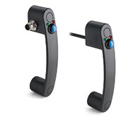
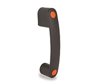
The M.2000-SWM handle is an ideal combination of ergonomics, functionality, and compactness.
In addition to the handle function, it integrates in a single product the function of signalling light column and control box with normally open or normally closed contacts. These handles are typically assembled on machine doors or protections. With the appropriate electrical connection, it is possible to configure the colour of the LED strip to indicate the status of the guard (IEC 60204-1).
Example:
- red: immediate action required to address a hazardous situation
- green: normal operational conditions
- yellow: wait, machinery shutting down or in a transitional phase
- blue: operator has made operation request (example: pressing key)
By pressing the button, the operator may request access, through external logic, to the protected area or reactive the machinery following an interruption.
Staff protection: the action NC (normally closed) switch ensures correct interruption of the circuit.
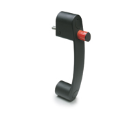
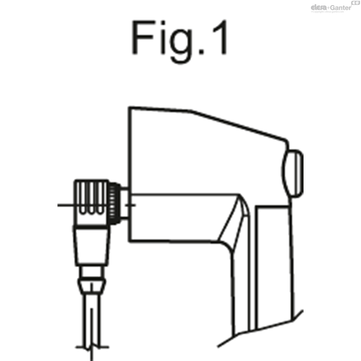
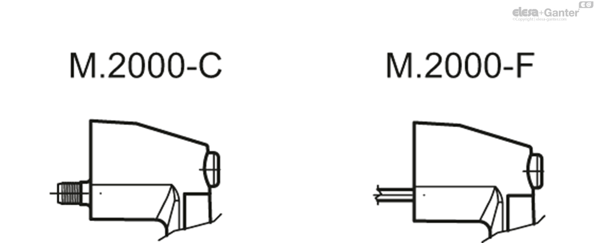
In case of use of an extension with angled connector, the direction of the cable output is shown in Fig.1.
Technical data
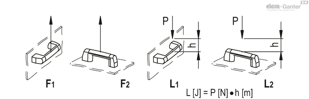
Tensile stress and impact strength: the values F1, F2, L1 and L2 indicated in the table were obtained during breaking tests carried out under the test conditions shown in the figure with ambient temperature.
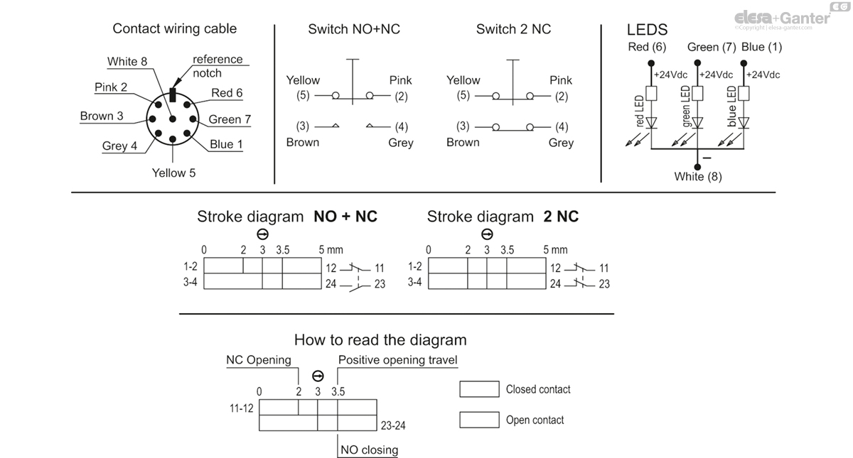
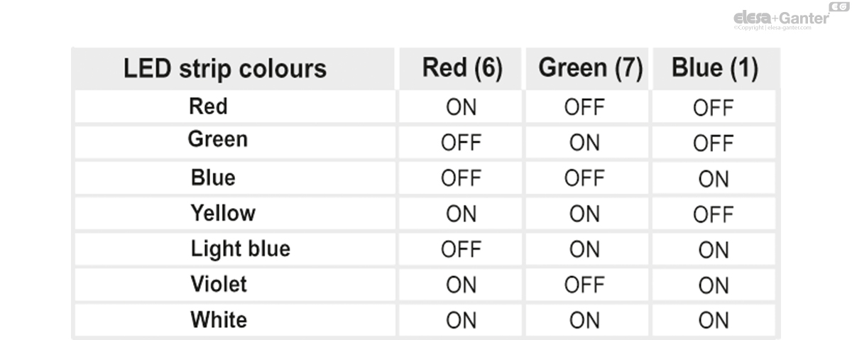
LED strip wiring instructions
With appropriate cabling, it is possible to obtain one of the 7 colours of the LED strip.
The common contact (8) corresponding to the white wire (cable version) must always be connected to the negative pole of the power supply. Contacts 6 (red wire), 7 (green wire), or 1 (blue wire) can be connected individually to the positive pole to respectively obtain the red, green, and blue colour of the LED strip, or connected simultaneously to obtain the remaining colours, as indicated in the table below. Other colours are possible by controlling the brightness of the individual channels with the PWM technique.
EC Declaration of Conformity
The object of the above declaration described above is in conformity with the relevant European Union harmonisation legislation:
- 2014/35/EU Low-voltage directive
- 2014/30/EU (EMC) Electromagnetic Compatibility Directive
- 2011/65/EU (RoHS) Restriction of the use of certain hazardous substances in electrical and electronic equipment
Harmonised standards and references to other technical specifications used in relation to which conformity is declared: EN 60947-5-1:2017


Accessories
Accessories on request
FC-M12x1: extensions with 8 pole M12 female axial connector.
Other executions
Special executions on request
- 2 NO contacts.
- LED operating voltage 12V.
- Quick release electrical contact.
- Non-IP handle, with reduced key action force (15N). To order this, add the suffix -N15 to the code and description of the desired standard execution.
Another standard execution
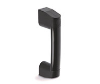
M.2000: single complementary handle without switch.
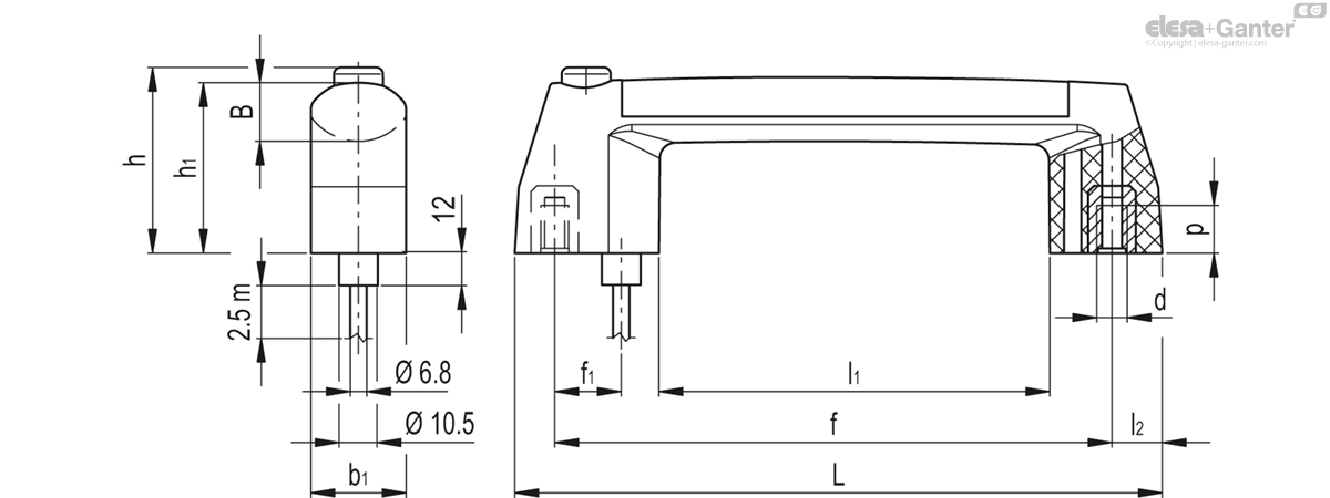
M.2000-1NC-1NO-SWM-F2.5
| L | f±1 | d | f1 | h | h1 | B | b1 | l1 | l2 | p | F1 [N] |
F2 [N] |
L1 [J] |
L2 [J] |
||||
|---|---|---|---|---|---|---|---|---|---|---|---|---|---|---|---|---|---|---|
| Code | Description | Actions | ||||||||||||||||
| 260811-C1 | M.2000/180-SWM-1NC+1NO-RGB-F2.5 | 212.5 | 180 | M6 | 29 | 70 | 65 | 24 | 35 | 113 | 20 | 12 | 700 | 900 | 7 | 6 | 320 |
|

Enquiry Now
To allow us to respond to your enquiry promptly, please provide all required information.
Related Products
-
 EBR-SWMHandle with monostable electrical switchTechnopolymerView Product
 -
EBR-SWBHandle with bistable electrical switchTechnopolymerView Product
-
M.2000Bridge handleSelf-extinguishing technopolymerView Product
-
EBR.Bridge handlesTechnopolymerView Product
-
EBR-CHHandle with safety locking deviceFor retractable sliding doors, technopolymerView Product
-
CFSW.Hinges with built-in safety switchSUPER-technopolymerView Product
-
CFSQHinges with built-in safety switchSUPER-technopolymerView Product