

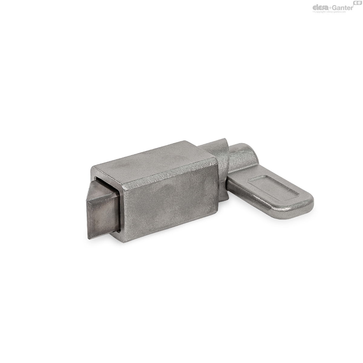
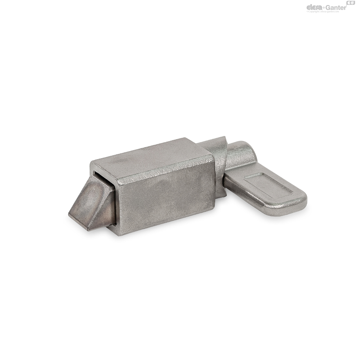
GN 724.1
Spring Latches
Steel / Stainless Steel, with Chamfered Pin, for Welding

Description
Specification
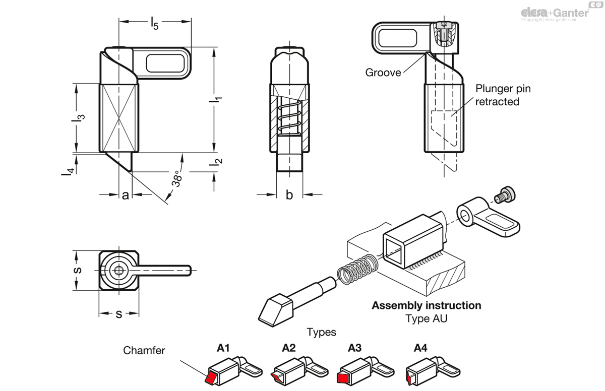
Types
- Type A1: Chamfer, top
- Type A2: Chamfer, bottom
- Type A3: Chamfer, right
- Type A4: Chamfer, left
- Type AU: Unmounted
Guide
- Steel precision casting ST
- Weldable, blackened
- Stainless steel precision casting AISI CF-8 NI
- Weldable
Latch arm
- Steel precision casting
- Zinc plated, blue passivated for ST
- Stainless steel precision casting AISI CF-8 for NI
Plunger pin
- Steel, hardened
- Zinc plated, blue passivated for ST
- Stainless steel AISI 431, hardened for NI
Socket button head screw DIN 7985
- Steel, zinc plated for ST
- Stainless steel AISI 304 for NI
Compression spring
Stainless steel AISI 316Ti
Information
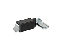
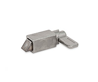
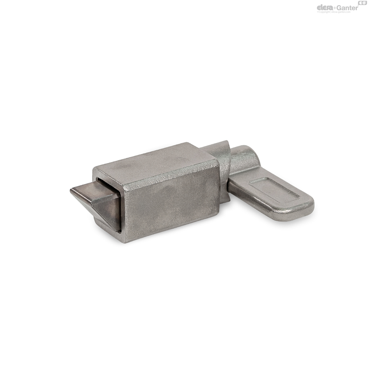
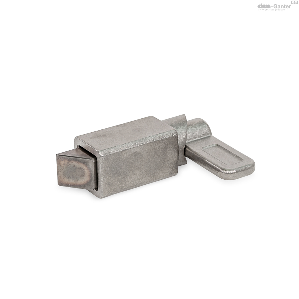
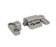
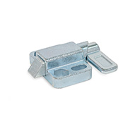
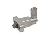
Spring latches GN 724.1 have a plunger pin with square cross-section, a latching surface on one side and a chamfer on the other. When moving in the direction of the chamfered pin, the plunger pin passes over grooves and edges, as the chamfered pin moves the plunger pin into the guide. The plunger pin automatically latches into place when moved toward the latching surface. The latching can be released by pulling the latch arm.
The notch at the upper end of the curve causes the latch to be held in place if the plunger pin needs to be kept temporarily from protruding.
The dimensional tolerances between plunger pin and guide are selected so that the functional reliability is guaranteed even after welding, applying a corrosion protection layer or in case of contamination. For type AU, the latching mechanism must be lubricated during installation, types A1, A2, A3 and A4 are pre-lubricated. The latching mechanism can be re-lubricated if necessary.
For fastening by welding, the unmounted type AU is particularly recommended to avoid changes to the microstructure of the material due to heating of the spring and plunger pin. In this case, the spring latch is assembled only after the surface treatment of the welded guide.
Technical information
- Application Example
- Range of Cam Action Indexing Plungers
- Stainless Steel Characteristics
GN 724.1-NI
| Color | b | s | a | l1 ≈ | l2 | l3 | l4 | l5 | Spring load in N≈ initial |
Spring load in N≈ end |
|||
|---|---|---|---|---|---|---|---|---|---|---|---|---|---|
| Code | Actions | ||||||||||||
| GN 724.1-13-20-A1-NI | A1 | 13 | 20 | 6.5 | 54 | 10 | 35 | 1 | 37 | 14 | 35 | 142 |
|
| GN 724.1-13-20-A2-NI | A2 | 13 | 20 | 6.5 | 54 | 10 | 35 | 1 | 37 | 14 | 35 | 142 |
|
| GN 724.1-13-20-A3-NI | A3 | 13 | 20 | 6.5 | 54 | 10 | 35 | 1 | 37 | 14 | 35 | 142 |
|
| GN 724.1-13-20-A4-NI | A4 | 13 | 20 | 6.5 | 54 | 10 | 35 | 1 | 37 | 14 | 35 | 142 |
|
| GN 724.1-13-20-AU-NI | AU | 13 | 20 | 6.5 | 54 | 10 | 35 | 1 | 37 | 14 | 35 | 142 |
|
| GN 724.1-20-30-A1-NI | A1 | 20 | 30 | 10 | 84 | 15 | 54 | 1.5 | 55 | 22 | 70 | 492 |
|
| GN 724.1-20-30-A2-NI | A2 | 20 | 30 | 10 | 84 | 15 | 54 | 1.5 | 55 | 22 | 70 | 492 |
|
| GN 724.1-20-30-A3-NI | A3 | 20 | 30 | 10 | 84 | 15 | 54 | 1.5 | 55 | 22 | 70 | 492 |
|
| GN 724.1-20-30-A4-NI | A4 | 20 | 30 | 10 | 84 | 15 | 54 | 1.5 | 55 | 22 | 70 | 492 |
|
| GN 724.1-20-30-AU-NI | AU | 20 | 30 | 10 | 84 | 15 | 54 | 1.5 | 55 | 22 | 70 | 492 |
|

Enquiry Now
To allow us to respond to your enquiry promptly, please provide all required information.
Related Products
-
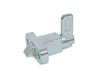 GN 724.2-STSpring LatchesSteel, with Chamfered Pin, with Flange for Surface MountingView Product
 -
 GN 724.3-NISpring LatchesStainless Steel, with Chamfered Pin, with Flange for Surface MountingView Product
 -
 GN 724.3-STSpring LatchesSteel, with Chamfered Pin, with Flange for Surface MountingView Product
 -
 GN 724.2-NISpring LatchesStainless Steel, with Chamfered Pin, with Flange for Surface MountingView Product

