GN 516.1
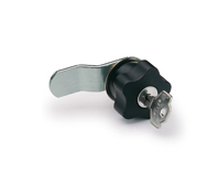
Rotary Clamping Latches
with Continuously Adjustable Latch Distance A


Description
Specification
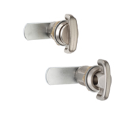
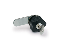
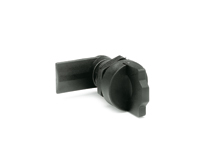
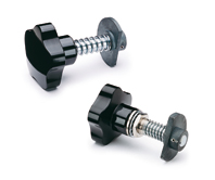
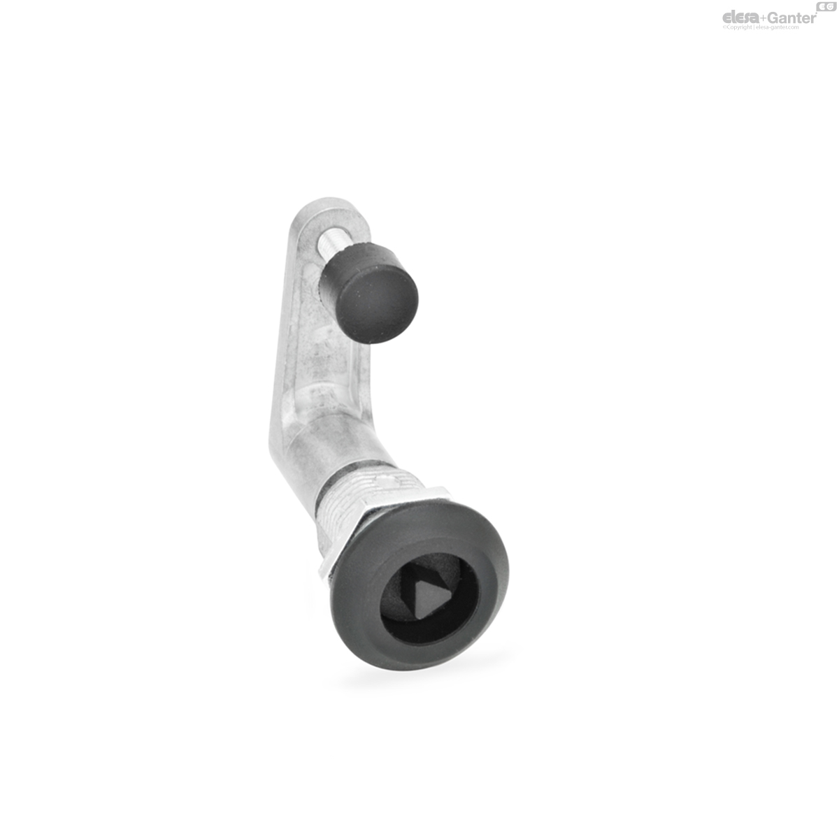
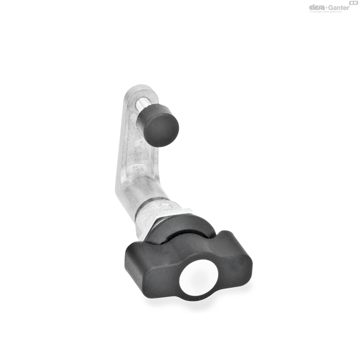
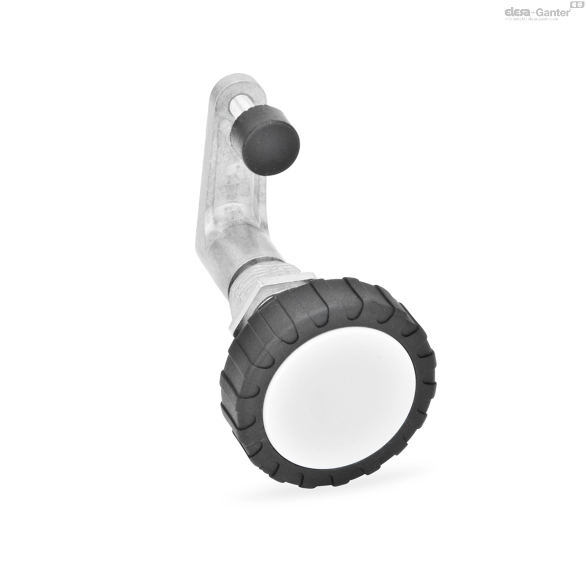
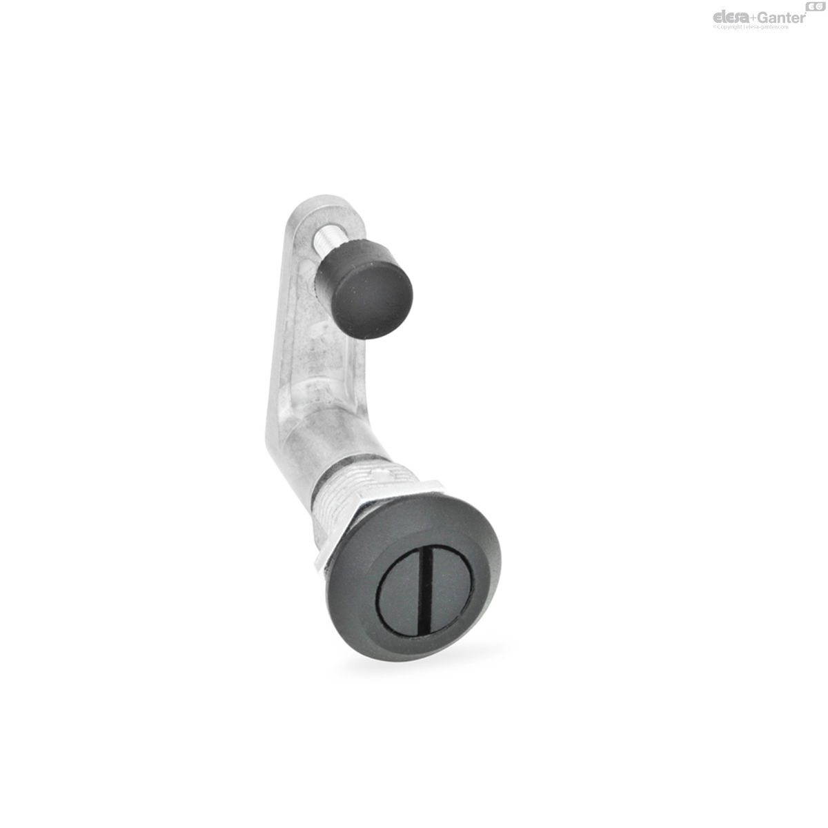
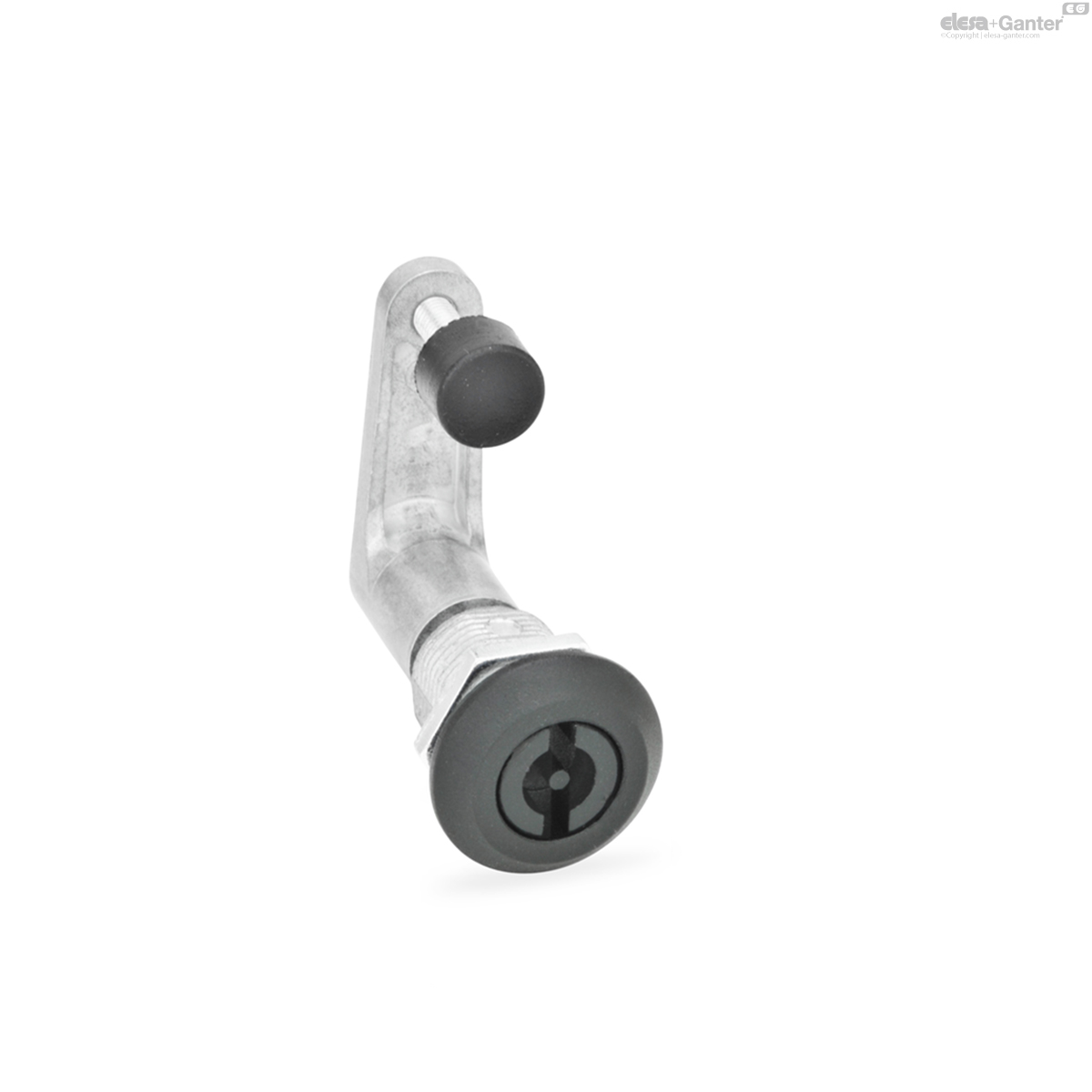
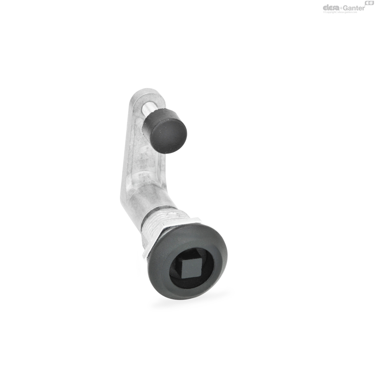
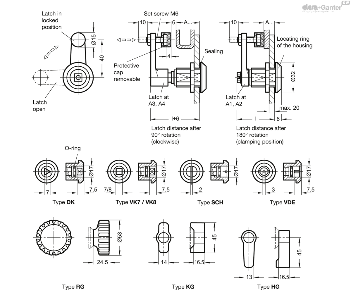
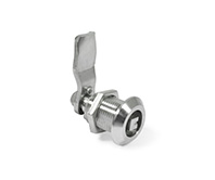
Types
- Type DK: Operation with triangular spindle (DK7)
- Type VK7: Operation with square spindle A/F7
- Type VK8: Operation with square spindle A/F8
- Type SCH: Operation with slot
- Type VDE: Operation with double bit
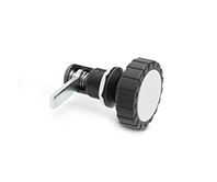
- Type RG: Operation with knurled knob GN 7336
- Type KG: Operation with wing knob
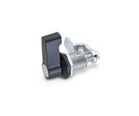
- Type HG: Operation with lever
Housing / Locking mechanism
Zinc die casting
Locating ring
plastic coated, black, textured finish
Latch
Zinc die casting
all handles (Type RG / KG / HG)
- Plastic (Polyamide PA) black, matt
- Cover cap light grey, matt
Protective cap CR Neoprene©
- 40 to 50 Shore A
- black
Protection class: IP 65
Information
The rotary clamping latches GN 516.1 have a closing mechanism which transfers the rotary movement of the operating element (key) into a 90° turn and then into a 6 mm linear stroke.
This mechanism is designed for common applications such as making a tight and vibration-proof interlock in the end position (retaining position) in connection with the protective cap.
A 10 mm adjustment within the latch distances A1 ... A4 can be achieved by the set screw M6. This covers a latch distance from 1 to 41 mm consistently.
Technical Information
- List of latch types
- IP Protection classes
- Plastic characteristics
Accessory
- Socket keys GN 119.2
- Protective caps GN 120
- Opening handles GN 120.1
Technical and Assembly Instructions

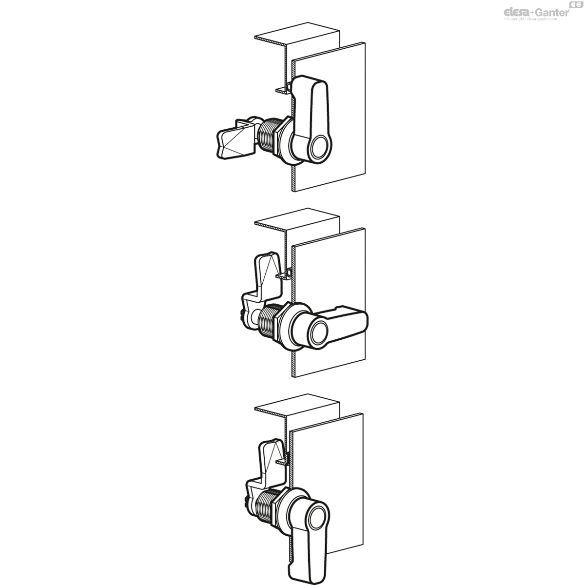
1. Latch in starting position.
2. The first 90° turn of the actuator / key moves the latch into the usual locking position.
3. Turning the actuator further by another 90° will lift the latch in linear direction by 6 mm, pulling the door leaf against the frame or the seal and generating a vibration-proof lock.
max. torque: 4.5 Nm
max. axial force: 340 N
max. static load: 340 N
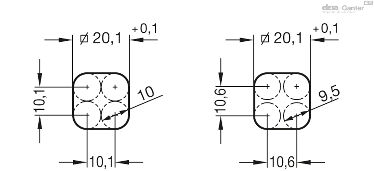
For installation, set a bore diameter in the door as shown in the outline drawing. Once assembled, the rotary clamping latch is pushed through the bore diameter from the front. The hexagonal nut can then be pushed over the latch from the back and bolted in place.
The installation bore diameter in the door leaf is usually generated by punching or laser application in series production.
For small series and steel sheets below 2 mm thickness, the sheet metal punshes GN 123 are the tool of choice.
The installation bore diameter can also be set by drilling / milling as shown in the outline drawings.
GN 516.1
| Color | Latch distance A in retaining position (clamping position) | Latch distance | |||
|---|---|---|---|---|---|
| Code | Actions | ||||
| GN 516.1-DK-A1 | DK | A 1 (l = 40.5) | 1 ... 11 | 80 |
|
| GN 516.1-DK-A2 | DK | A 2 (l = 40.5) | 11 ... 21 | 100 |
|
| GN 516.1-DK-A3 | DK | A 3 (l = 56) | 21 ... 31 | 102 |
|
| GN 516.1-DK-A4 | DK | A 4 (l = 56) | 31 ... 41 | 118 |
|
| GN 516.1-HG-A1 | HG | A 1 (l = 40.5) | 1 ... 11 | 110 |
|
| GN 516.1-HG-A2 | HG | A 2 (l = 40.5) | 11 ... 21 | 100 |
|
| GN 516.1-HG-A3 | HG | A 3 (l = 56) | 21 ... 31 | 120 |
|
| GN 516.1-HG-A4 | HG | A 4 (l = 56) | 31 ... 41 | 133 |
|
| GN 516.1-KG-A1 | KG | A 1 (l = 40.5) | 1 ... 11 | 120 |
|
| GN 516.1-KG-A2 | KG | A 2 (l = 40.5) | 11 ... 21 | 120 |
|
| GN 516.1-KG-A3 | KG | A 3 (l = 56) | 21 ... 31 | 140 |
|
| GN 516.1-KG-A4 | KG | A 4 (l = 56) | 31 ... 41 | 129 |
|
| GN 516.1-RG-A1 | RG | A 1 (l = 40.5) | 1 ... 11 | 140 |
|
| GN 516.1-RG-A2 | RG | A 2 (l = 40.5) | 11 ... 21 | 123 |
|
| GN 516.1-RG-A3 | RG | A 3 (l = 56) | 21 ... 31 | 120 |
|
| GN 516.1-RG-A4 | RG | A 4 (l = 56) | 31 ... 41 | 120 |
|
| GN 516.1-SCH-A1 | SCH | A 1 (l = 40.5) | 1 ... 11 | 120 |
|
| GN 516.1-SCH-A2 | SCH | A 2 (l = 40.5) | 11 ... 21 | 112 |
|
| GN 516.1-SCH-A3 | SCH | A 3 (l = 56) | 21 ... 31 | 127 |
|
| GN 516.1-SCH-A4 | SCH | A 4 (l = 56) | 31 ... 41 | 125 |
|
| GN 516.1-VDE-A1 | VDE | A 1 (l = 40.5) | 1 ... 11 | 120 |
|
| GN 516.1-VDE-A2 | VDE | A 2 (l = 40.5) | 11 ... 21 | 90 |
|
| GN 516.1-VDE-A3 | VDE | A 3 (l = 56) | 21 ... 31 | 120 |
|
| GN 516.1-VDE-A4 | VDE | A 4 (l = 56) | 31 ... 41 | 132 |
|
| GN 516.1-VK7-A1 | VK7 | A 1 (l = 40.5) | 1 ... 11 | 106 |
|
| GN 516.1-VK7-A2 | VK7 | A 2 (l = 40.5) | 11 ... 21 | 89 |
|
| GN 516.1-VK7-A3 | VK7 | A 3 (l = 56) | 21 ... 31 | 103 |
|
| GN 516.1-VK7-A4 | VK7 | A 4 (l = 56) | 31 ... 41 | 102 |
|
| GN 516.1-VK8-A1 | VK8 | A 1 (l = 40.5) | 1 ... 11 | 100 |
|
| GN 516.1-VK8-A2 | VK8 | A 2 (l = 40.5) | 11 ... 21 | 106 |
|
| GN 516.1-VK8-A3 | VK8 | A 3 (l = 56) | 21 ... 31 | 120 |
|
| GN 516.1-VK8-A4 | VK8 | A 4 (l = 56) | 31 ... 41 | 118 |
|

Enquiry Now
To allow us to respond to your enquiry promptly, please provide all required information.
Related Products
-
 GN 116.1Rotary clamping latchesView Product
 -
 CM.Compression latches with key-type knobZinc alloyView Product
 -
VC.308Lever latchesTechnopolymer knob with lockView Product
-
 GN 516Rotary clamping latchesOperation with socket key or operating elementView Product
 -
CMT.AE-V0Lever latches with fold-away knobTechnopolymerView Product
-
VCK.Cam latches with knobSteel or stainless steel camView Product
-
 GN 516.5Stainless Steel-Rotary clamping latchesOperation with socket key or operating elementView Product
 -
VC.309Lever latchesTechnopolymer knob with lockView Product