

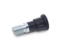
GN 514
Locking Plungers
Steel / Stainless Steel, with Cardioid Curve Mechanism (Retractable Pen principle)

Description
Specification
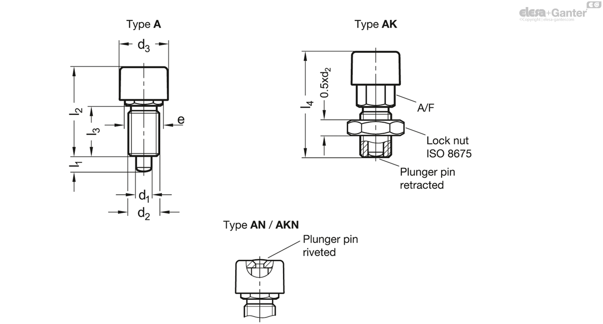
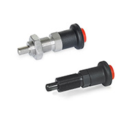
Types
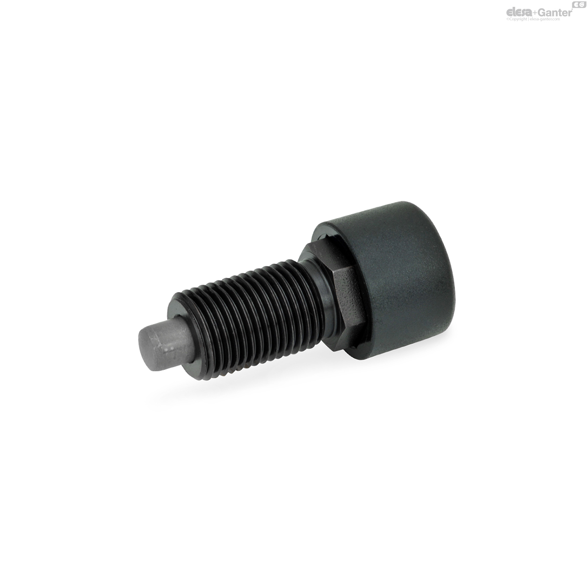
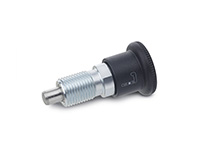
Type A: With plastic knob, without lock nut
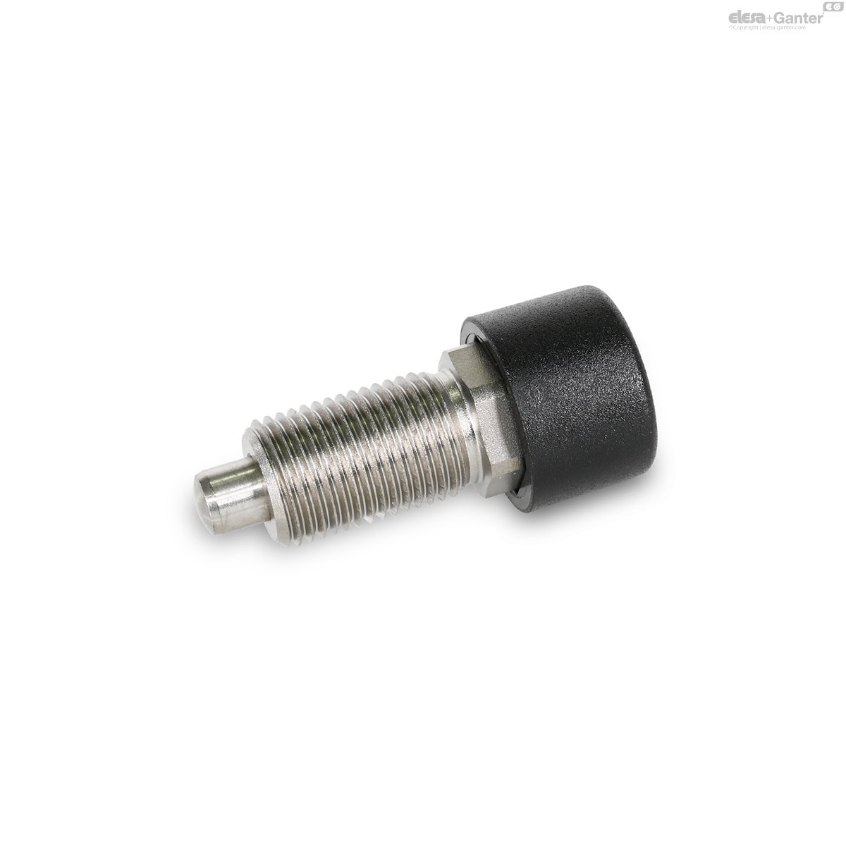
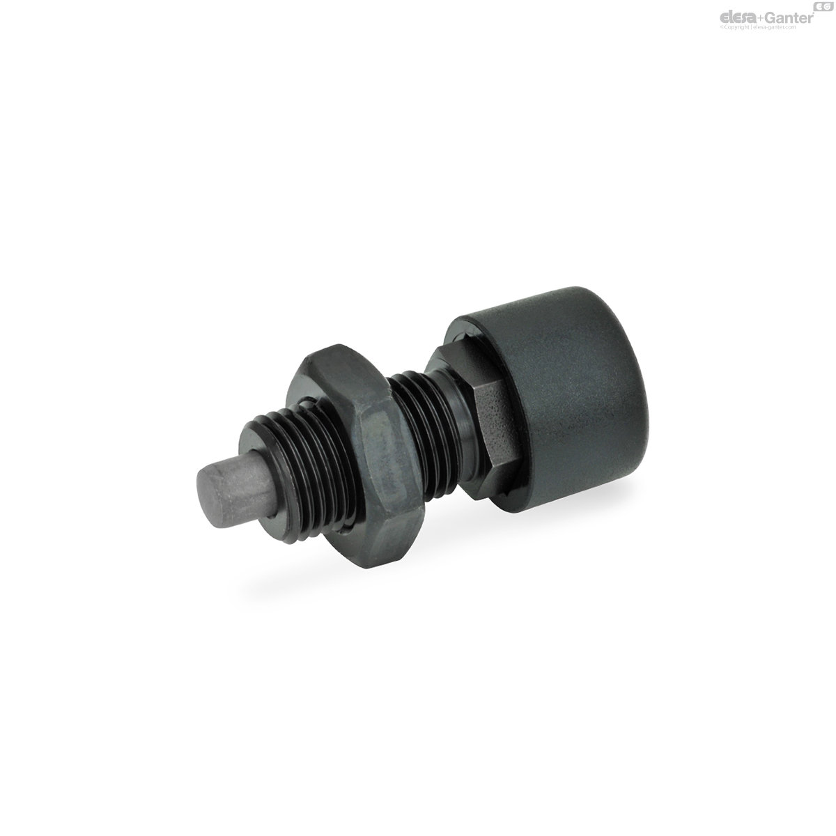
Type AK: With plastic knob, with lock nut
Type AN: With stainless steel knob, without lock nut
Type AKN: With stainless steel knob, with lock nut
Steel
Blackened
- Plunger pin
Steel, nitrided
- Compression spring
Stainless steel AISI 301
Stainless steel AISI 316 A4
- Plunger pin
Stainless steel AISI 316
Case hardened
- Compression spring
Stainless steel 316Ti
Knob (type A / AK)
Plastic (Polyamide PA)
- Black, matte finish
- Not removable
Knob (type AN / AKN)
Stainless steel AISI 316
Not removable
Information
Locking plungers GN 514 feature a cardioid curve mechanism based on the principle of a retractable pen. They offer very ergonomic operation that requires only repeated pressing of the knob. Thanks to their functional principle, they are well suited for use in tight conditions and are also easy to protect against improper operation, if necessary.
First the plunger pin is brought into the protruding position by pressing the knob. In this position, the cardioid curve mechanism automatically engages to lock the part. Pressing the knob again unlocks the mechanism since the plunger pin retracts automatically by spring force once the button is released. The plunger pin must not be subjected to any axial forces and must move easily.
The stainless steel design is suitable for applications in highly corrosive environments thanks to the A4 materials used.
- Range of indexing plungers
Technical information
- Load Rating Information
- ISO-Fundamental Tolerances
- Plastic Characteristics
- Stainless Steel Characteristics
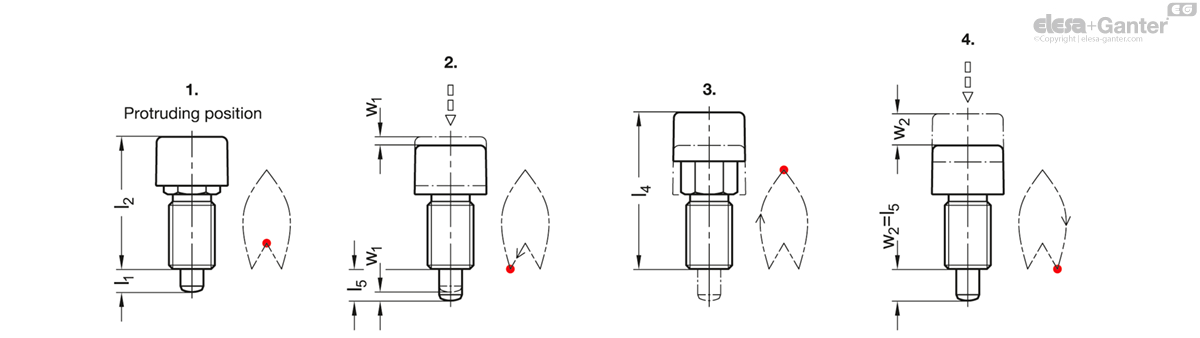
Description of function
1. In the protruding position, the plunger pin protrudes by distance l1 and is locked.
2. The knob is pressed by distance w1, thereby unlocking the plunger pin.
3. Then the plunger pin is retracted by the compression spring and held in the retracted position.
4. The knob is pressed by distance w2 and locks again in the protruding position after release.
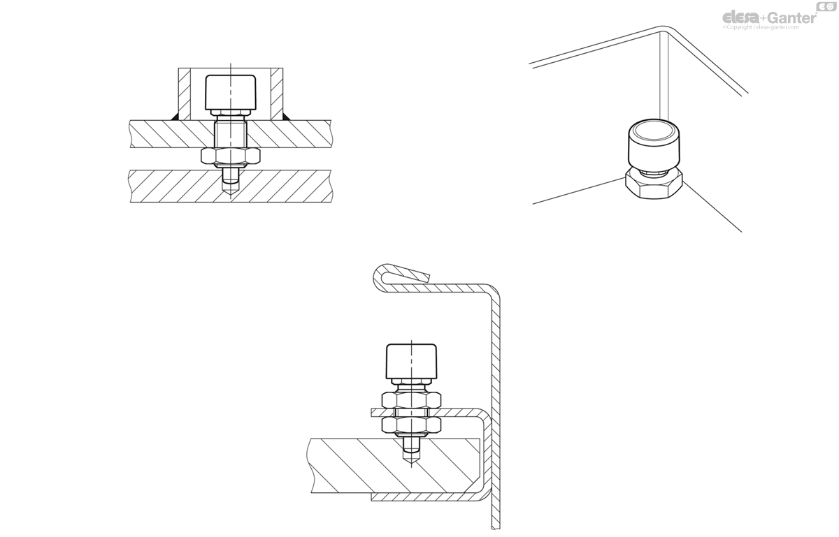
Application example
GN 514
| Color | d1 Pin -0.02/-0.05 Bore H7 |
d2 | d3 | e | l1 | l2 | l3 | l4 | l5 | A/F | w1 | w2 | Spring load in N≈ initial |
Spring load in N≈ end |
|||
|---|---|---|---|---|---|---|---|---|---|---|---|---|---|---|---|---|---|
| Code | Actions | ||||||||||||||||
| GN 514-6-A | A | 6 | M 12 x 1.5 | 19 | 15 | 6 | 38 | 19.5 | 44.5 | 9 | 13 | 3 | 9 | 8.5 | 25 | 28 |
|
| GN 514-6-AK | AK | 6 | M 12 x 1.5 | 19 | 15 | 6 | 38 | 19.5 | 44.5 | 9 | 13 | 3 | 9 | 8.5 | 25 | 30 |
|
| GN 514-8-A | A | 8 | M 16 x 1.5 | 25 | 19 | 8 | 46 | 25.5 | 54.5 | 11 | 17 | 3 | 11 | 18 | 44 | 61 |
|
| GN 514-8-AK | AK | 8 | M 16 x 1.5 | 25 | 19 | 8 | 46 | 25.5 | 54.5 | 11 | 17 | 3 | 11 | 18 | 44 | 79 |
|

Enquiry Now
To allow us to respond to your enquiry promptly, please provide all required information.
Related Products
-
 GN 816Locking plungersPin in normal position protrudedView Product
 -
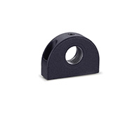
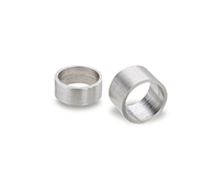 GN 609.5Stainless Steel-Distance bushingsfor mounting indexing plungers / cam action indexing plungersView Product
 -
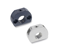 GN 612.1Mounting blocksSteel / Stainless Steel, for indexing plungers / cam action indexing plungersView Product
 -
 GN 412.1Mounting blocksfor indexing plungers / cam action indexing plungersView Product
 -
 GN 816.1Locking plungersPin in normal position retractedView Product
 -
 GN 414Indexing plungersSteel / Stainless Steel, with safety lock, unlocking with push-buttonView Product
 -
 GN 412.2Positioning bushingsfor indexing plungers / cam action indexing plungersView Product
 -
 GN 909Thin Hex NutsSteel, for Indexing Plungers / Cam Action Indexing PlungersView Product

