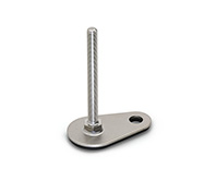
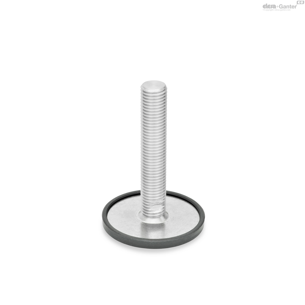
GN 44
Leveling Feet
Stainless Steel

GN 44-S/SK
Leveling Feet
With / without nut, external hex at the bottom
GN 44-T/TK
Leveling Feet
With / without nut, wrench flat at the bottom
Description
Specification
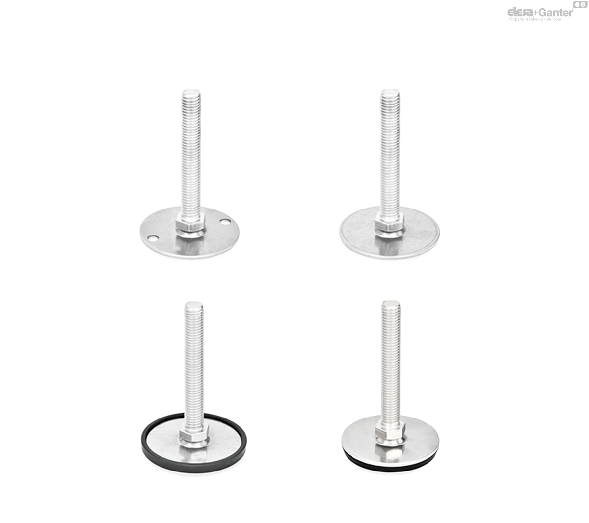
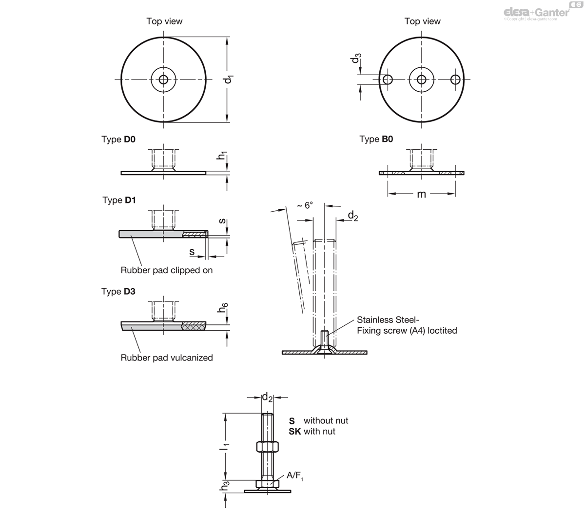
Types (Base plate)
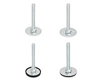
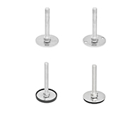
- Type D0: Without rubber pad
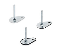
- Type B0: Without rubber pad, with 2 fixing holes
- Type D1: With rubber pad, clipped on, black
- Type D3: With rubber pad, vulcanized, black
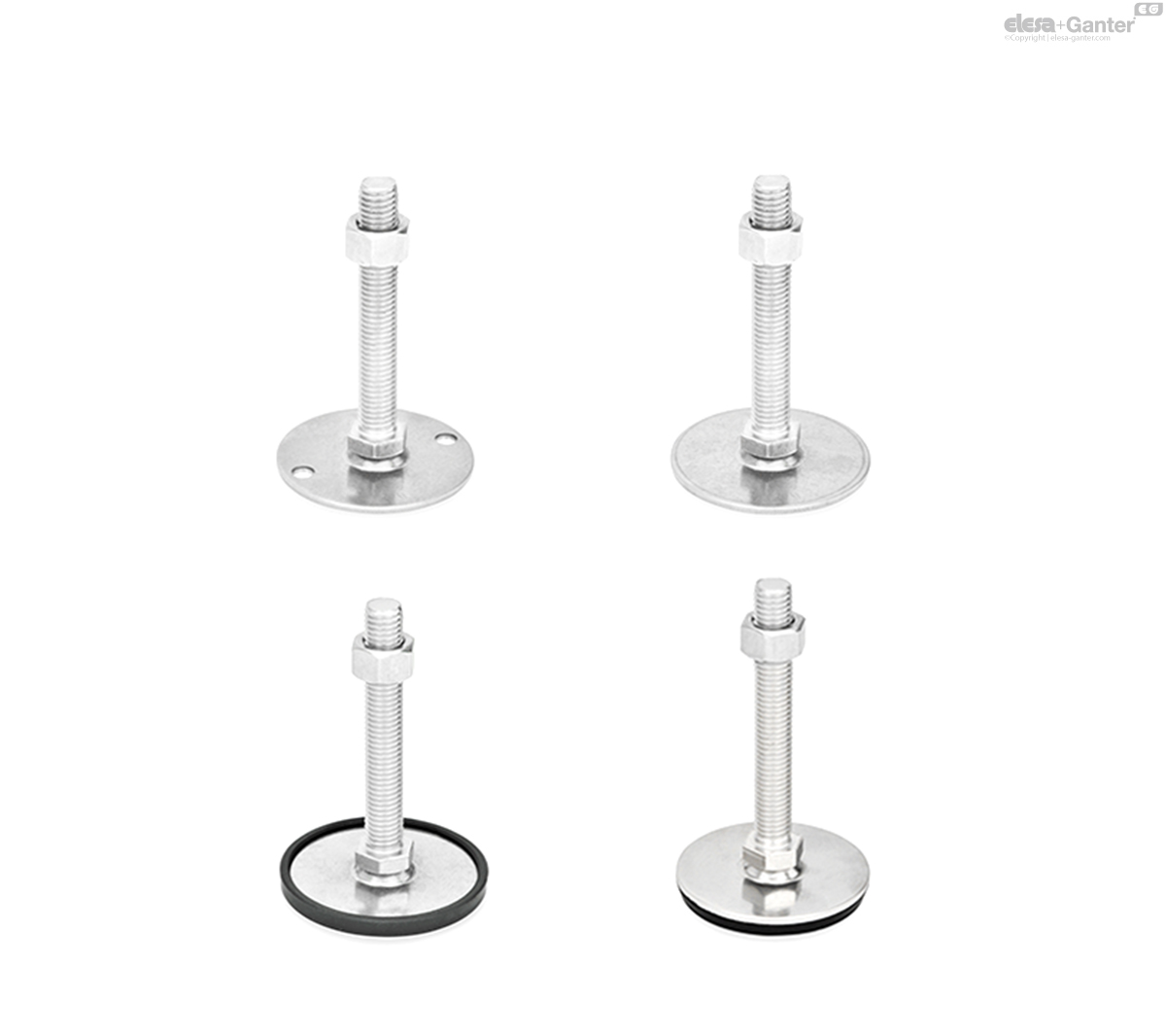
Versions of threaded stem
- Version S: Without nut, external hex at the bottom
- Version SK: With nut, external hex at the bottom
- Version T: Without nut, wrench flat at the bottom
- Version TK: With nut, wrench flat at the bottom
Base plate
Stainless steel AISI 316 L
Plain, ground
Threaded stem
Stainless steel AISI 316 L
Hex nut ISO 4032
Stainless steel
Rubber cap
Clipped on
Black, TPE (Santoprene®)
≈ 80 Shore A
Rubber pad
Vulcanized
Black, NBR (Perbunan®)
70±5 Shore A
Information
Leveling feet GN 44 are for use in aggressive environments. The range of combinations of base plates and adjustable spindle versions allows these leveling feat to be used in every situation.
The base plate with the rubber pad protects sensitive surfaces and reduces lateral slippage. The type B0 can also be fastened to the mounting surface through two holes.
The leveling feet are supplied fully assembled and are not removable.
Technical information
- Plastic Characteristics
- Stainless Steel Characteristics
Load Rating of Leveling Feet
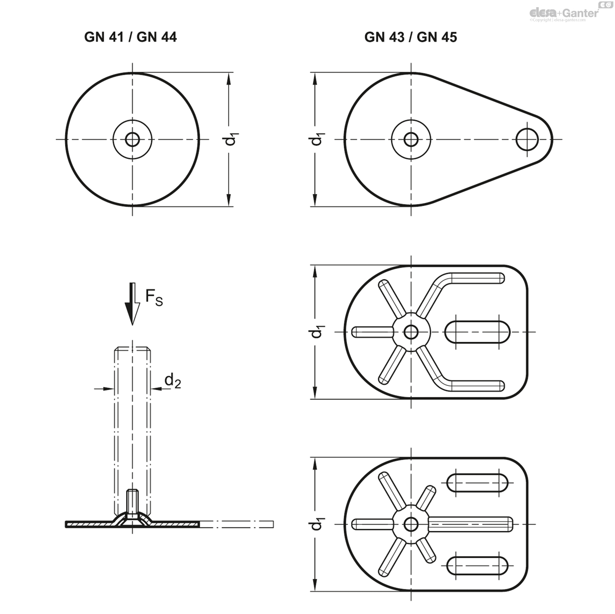
| d1 | - | - | d2 | Static load in kN | - | - | - | - |
| GN 41 / GN 44 | GN 43 / GN 45 | GN 43 | - | Versions of threaded stem | - | - | - | - |
| - | Drope shape | Rectangular shape | - | S / SK | T / TK and U / UK | V / VK | W | X |
| 40 | - | - | M 8 | 8 | - | - | - | 8 |
| 40 | - | - | M 10 | 12 | - | - | - | 12 |
| 40 | - | - | M 12 | 12 | - | - | - | 12 |
| 40 | - | - | M 16 | - | 12 | - | - | 12 |
| 50 | 50 | - | M 8 | 8 | - | - | - | 8 |
| 50 | 50 | - | M 10 | 14 | - | - | - | 14 |
| 50 | 50 | - | M 12 | 14 | - | - | - | 14 |
| 50 | 50 | - | M 16 | - | 14 | - | - | 14 |
| 60 | 60 | - | M 8 | 8 | - | - | - | 8 |
| 60 | 60 | - | M 10 | 14 | - | - | - | 14 |
| 60 | 60 | - | M 12 | 16 | - | - | - | 16 |
| 60 | 60 | - | M 16 | - | 16 | 16 | 16 | 16 |
| 80 | 80 | 80 | M 8 | 8 | - | - | - | 8 |
| 80 | 80 | 80 | M 10 | 14 | - | - | - | 14 |
| 80 | 80 | 80 | M 12 | 20 | - | - | - | 20 |
| 80 | 80 | 80 | M 16 | - | 20 | 20 | 20 | 20 |
| 80 | 80 | 80 | M 20 | - | 20 | 20 | 20 | 20 |
| 80 | 80 | 80 | M 24 | - | 22 | 22 | 22 | - |
The static load bearing capacity given in the table rests on a test series in which the load has been applied perpendicular to the base plate (without rubber underlay). For the values given in the table, the strain relief may result in minor deformations of the base plate.
Bending and buckling stress which often occurs in practice results in a lower load bearing capacity of the adjustment spindle and may have to be taken into account.
Also, the spindle strength is assumed to be ≥ 500 N/mm2.
The details given on strength are nonbinding guide values without any liability. In general, they do not constitute a warranty of quality.
The user must determine from case to case if a product is suitable for the intended purpose or use. Environmental factors may influence the stated values.
Versions of threaded stem
| Versions of threaded stem | |
| S / SK: External hex at the bottom at d2 M 8, M 10, M 12 | T / TK: Wrench flat at the bottom at d2 M 16, M 20, M 24, M 30 |
GN 44-S/SK
| Color | d1 | d2 | l1 | d3 | h1 | h3 | h6 | m | s | A/F 1 | Static load in kN |
|||
|---|---|---|---|---|---|---|---|---|---|---|---|---|---|---|
| Code | Actions | |||||||||||||
| GN 44-40-M8-40-B0-S | Type S | 40 | M 8 | 40 | 5.4 | 2 | 11 | - | 30 | - | 17 | 8 | 62 |
|
| GN 44-40-M8-40-B0-SK | SK | 40 | M 8 | 40 | 5.4 | 2 | 11 | - | 30 | - | 17 | 8 | 71 |
|
| GN 44-40-M8-40-D0-S | Type S | 40 | M 8 | 40 | - | 2 | 11 | - | 30 | - | 17 | 8 | 63 |
|
| GN 44-40-M8-40-D0-SK | SK | 40 | M 8 | 40 | - | 2 | 11 | - | 30 | - | 17 | 8 | 72 |
|
| GN 44-40-M8-40-D1-S | Type S | 40 | M 8 | 40 | - | 2 | 11 | - | 30 | 1.5 | 17 | 8 | 46 |
|
| GN 44-40-M8-40-D1-SK | SK | 40 | M 8 | 40 | - | 2 | 11 | - | 30 | 1.5 | 17 | 8 | 50 |
|
| GN 44-40-M8-40-D3-S | Type S | 40 | M 8 | 40 | - | 2 | 11 | 3.5 | 30 | - | 17 | 8 | 48 |
|
| GN 44-40-M8-40-D3-SK | SK | 40 | M 8 | 40 | - | 2 | 11 | 3.5 | 30 | - | 17 | 8 | 50 |
|
| GN 44-40-M8-50-B0-S | Type S | 40 | M 8 | 50 | 5.4 | 2 | 11 | - | 30 | - | 17 | 8 | 66 |
|
| GN 44-40-M8-50-B0-SK | SK | 40 | M 8 | 50 | 5.4 | 2 | 11 | - | 30 | - | 17 | 8 | 75 |
|
| GN 44-40-M8-50-D0-S | Type S | 40 | M 8 | 50 | - | 2 | 11 | - | 30 | - | 17 | 8 | 56 |
|
| GN 44-40-M8-50-D0-SK | SK | 40 | M 8 | 50 | - | 2 | 11 | - | 30 | - | 17 | 8 | 75 |
|
| GN 44-40-M8-50-D1-S | Type S | 40 | M 8 | 50 | - | 2 | 11 | - | 30 | 1.5 | 17 | 8 | 49 |
|
| GN 44-40-M8-50-D1-SK | SK | 40 | M 8 | 50 | - | 2 | 11 | - | 30 | 1.5 | 17 | 8 | 78 |
|
| GN 44-40-M8-50-D3-S | Type S | 40 | M 8 | 50 | - | 2 | 11 | 3.5 | 30 | - | 17 | 8 | 70 |
|
| GN 44-40-M8-50-D3-SK | SK | 40 | M 8 | 50 | - | 2 | 11 | 3.5 | 30 | - | 17 | 8 | 55 |
|
| GN 44-40-M8-63-B0-S | Type S | 40 | M 8 | 63 | 5.4 | 2 | 11 | - | 30 | - | 17 | 8 | 69 |
|
| GN 44-40-M8-63-B0-SK | SK | 40 | M 8 | 63 | 5.4 | 2 | 11 | - | 30 | - | 17 | 8 | 78 |
|
| GN 44-40-M8-63-D0-S | Type S | 40 | M 8 | 63 | - | 2 | 11 | - | 30 | - | 17 | 8 | 50 |
|
| GN 44-40-M8-63-D0-SK | SK | 40 | M 8 | 63 | - | 2 | 11 | - | 30 | - | 17 | 8 | 55 |
|
| GN 44-40-M8-63-D1-S | Type S | 40 | M 8 | 63 | - | 2 | 11 | - | 30 | 1.5 | 17 | 8 | 55 |
|
| GN 44-40-M8-63-D1-SK | SK | 40 | M 8 | 63 | - | 2 | 11 | - | 30 | 1.5 | 17 | 8 | 60 |
|
| GN 44-40-M8-63-D3-S | Type S | 40 | M 8 | 63 | - | 2 | 11 | 3.5 | 30 | - | 17 | 8 | 74 |
|
| GN 44-40-M8-63-D3-SK | SK | 40 | M 8 | 63 | - | 2 | 11 | 3.5 | 30 | - | 17 | 8 | 60 |
|
| GN 44-40-M10-50-B0-S | Type S | 40 | M 10 | 50 | 5.4 | 2 | 11 | - | 30 | - | 17 | 12 | 55 |
|
| GN 44-40-M10-50-B0-SK | SK | 40 | M 10 | 50 | 5.4 | 2 | 11 | - | 30 | - | 17 | 12 | 64 |
|
| GN 44-40-M10-50-D0-S | Type S | 40 | M 10 | 50 | - | 2 | 11 | - | 30 | - | 17 | 12 | 55 |
|
| GN 44-40-M10-50-D0-SK | SK | 40 | M 10 | 50 | - | 2 | 11 | - | 30 | - | 17 | 12 | 64 |
|
| GN 44-40-M10-50-D1-S | Type S | 40 | M 10 | 50 | - | 2 | 11 | - | 30 | 1.5 | 17 | 12 | 58 |
|
| GN 44-40-M10-50-D1-SK | SK | 40 | M 10 | 50 | - | 2 | 11 | - | 30 | 1.5 | 17 | 12 | 67 |
|
| GN 44-40-M10-50-D3-S | Type S | 40 | M 10 | 50 | - | 2 | 11 | 3.5 | 30 | - | 17 | 12 | 59 |
|
| GN 44-40-M10-50-D3-SK | SK | 40 | M 10 | 50 | - | 2 | 11 | 3.5 | 30 | - | 17 | 12 | 68 |
|
| GN 44-40-M10-60-B0-S | Type S | 40 | M 10 | 60 | 5.4 | 2 | 11 | - | 30 | - | 17 | 12 | 79 |
|
| GN 44-40-M10-60-B0-SK | SK | 40 | M 10 | 60 | 5.4 | 2 | 11 | - | 30 | - | 17 | 12 | 88 |
|
| GN 44-40-M10-60-D0-S | Type S | 40 | M 10 | 60 | - | 2 | 11 | - | 30 | - | 17 | 12 | 80 |
|
| GN 44-40-M10-60-D0-SK | SK | 40 | M 10 | 60 | - | 2 | 11 | - | 30 | - | 17 | 12 | 89 |
|
| GN 44-40-M10-60-D1-S | Type S | 40 | M 10 | 60 | - | 2 | 11 | - | 30 | 1.5 | 17 | 12 | 83 |
|
| GN 44-40-M10-60-D1-SK | SK | 40 | M 10 | 60 | - | 2 | 11 | - | 30 | 1.5 | 17 | 12 | 92 |
|
| GN 44-40-M10-60-D3-S | Type S | 40 | M 10 | 60 | - | 2 | 11 | 3.5 | 30 | - | 17 | 12 | 70 |
|
| GN 44-40-M10-60-D3-SK | SK | 40 | M 10 | 60 | - | 2 | 11 | 3.5 | 30 | - | 17 | 12 | 92 |
|
| GN 44-40-M10-80-B0-S | Type S | 40 | M 10 | 80 | 5.4 | 2 | 11 | - | 30 | - | 17 | 12 | 89 |
|
| GN 44-40-M10-80-B0-SK | SK | 40 | M 10 | 80 | 5.4 | 2 | 11 | - | 30 | - | 17 | 12 | 98 |
|
| GN 44-40-M10-80-D0-S | Type S | 40 | M 10 | 80 | - | 2 | 11 | - | 30 | - | 17 | 12 | 73 |
|
| GN 44-40-M10-80-D0-SK | SK | 40 | M 10 | 80 | - | 2 | 11 | - | 30 | - | 17 | 12 | 99 |
|
| GN 44-40-M10-80-D1-S | Type S | 40 | M 10 | 80 | - | 2 | 11 | - | 30 | 1.5 | 17 | 12 | 93 |
|
| GN 44-40-M10-80-D1-SK | SK | 40 | M 10 | 80 | - | 2 | 11 | - | 30 | 1.5 | 17 | 12 | 80 |
|
| GN 44-40-M10-80-D3-S | Type S | 40 | M 10 | 80 | - | 2 | 11 | 3.5 | 30 | - | 17 | 12 | 94 |
|
| GN 44-40-M10-80-D3-SK | SK | 40 | M 10 | 80 | - | 2 | 11 | 3.5 | 30 | - | 17 | 12 | 94 |
|
| GN 44-40-M10-100-B0-S | Type S | 40 | M 10 | 100 | 5.4 | 2 | 11 | - | 30 | - | 17 | 12 | 79 |
|
| GN 44-40-M10-100-B0-SK | SK | 40 | M 10 | 100 | 5.4 | 2 | 11 | - | 30 | - | 17 | 12 | 88 |
|
| GN 44-40-M10-100-D0-S | Type S | 40 | M 10 | 100 | - | 2 | 11 | - | 30 | - | 17 | 12 | 80 |
|
| GN 44-40-M10-100-D0-SK | SK | 40 | M 10 | 100 | - | 2 | 11 | - | 30 | - | 17 | 12 | 89 |
|
| GN 44-40-M10-100-D1-S | Type S | 40 | M 10 | 100 | - | 2 | 11 | - | 30 | 1.5 | 17 | 12 | 83 |
|
| GN 44-40-M10-100-D1-SK | SK | 40 | M 10 | 100 | - | 2 | 11 | - | 30 | 1.5 | 17 | 12 | 92 |
|
| GN 44-40-M10-100-D3-S | Type S | 40 | M 10 | 100 | - | 2 | 11 | 3.5 | 30 | - | 17 | 12 | 84 |
|
| GN 44-40-M10-100-D3-SK | SK | 40 | M 10 | 100 | - | 2 | 11 | 3.5 | 30 | - | 17 | 12 | 93 |
|
| GN 44-40-M12-60-B0-S | Type S | 40 | M 12 | 60 | 5.4 | 2 | 11 | - | 30 | - | 17 | 12 | 92 |
|
| GN 44-40-M12-60-B0-SK | SK | 40 | M 12 | 60 | 5.4 | 2 | 11 | - | 30 | - | 17 | 12 | 101 |
|
| GN 44-40-M12-60-D0-S | Type S | 40 | M 12 | 60 | - | 2 | 11 | - | 30 | - | 17 | 12 | 93 |
|
| GN 44-40-M12-60-D0-SK | SK | 40 | M 12 | 60 | - | 2 | 11 | - | 30 | - | 17 | 12 | 102 |
|
| GN 44-40-M12-60-D1-S | Type S | 40 | M 12 | 60 | - | 2 | 11 | - | 30 | 1.5 | 17 | 12 | 96 |
|
| GN 44-40-M12-60-D1-SK | SK | 40 | M 12 | 60 | - | 2 | 11 | - | 30 | 1.5 | 17 | 12 | 105 |
|
| GN 44-40-M12-60-D3-S | Type S | 40 | M 12 | 60 | - | 2 | 11 | 3.5 | 30 | - | 17 | 12 | 96 |
|
| GN 44-40-M12-60-D3-SK | SK | 40 | M 12 | 60 | - | 2 | 11 | 3.5 | 30 | - | 17 | 12 | 105 |
|
| GN 44-40-M12-80-B0-S | Type S | 40 | M 12 | 80 | 5.4 | 2 | 11 | - | 30 | - | 17 | 12 | 87 |
|
| GN 44-40-M12-80-B0-SK | SK | 40 | M 12 | 80 | 5.4 | 2 | 11 | - | 30 | - | 17 | 12 | 96 |
|
| GN 44-40-M12-80-D0-S | Type S | 40 | M 12 | 80 | - | 2 | 11 | - | 30 | - | 17 | 12 | 87 |
|
| GN 44-40-M12-80-D0-SK | SK | 40 | M 12 | 80 | - | 2 | 11 | - | 30 | - | 17 | 12 | 96 |
|
| GN 44-40-M12-80-D1-S | Type S | 40 | M 12 | 80 | - | 2 | 11 | - | 30 | 1.5 | 17 | 12 | 90 |
|
| GN 44-40-M12-80-D1-SK | SK | 40 | M 12 | 80 | - | 2 | 11 | - | 30 | 1.5 | 17 | 12 | 99 |
|
| GN 44-40-M12-80-D3-S | Type S | 40 | M 12 | 80 | - | 2 | 11 | 3.5 | 30 | - | 17 | 12 | 91 |
|
| GN 44-40-M12-80-D3-SK | SK | 40 | M 12 | 80 | - | 2 | 11 | 3.5 | 30 | - | 17 | 12 | 100 |
|
| GN 44-40-M12-100-B0-S | Type S | 40 | M 12 | 100 | 5.4 | 2 | 11 | - | 30 | - | 17 | 12 | 121 |
|
| GN 44-40-M12-100-B0-SK | SK | 40 | M 12 | 100 | 5.4 | 2 | 11 | - | 30 | - | 17 | 12 | 130 |
|
| GN 44-40-M12-100-D0-S | Type S | 40 | M 12 | 100 | - | 2 | 11 | - | 30 | - | 17 | 12 | 121 |
|
| GN 44-40-M12-100-D0-SK | SK | 40 | M 12 | 100 | - | 2 | 11 | - | 30 | - | 17 | 12 | 130 |
|
| GN 44-40-M12-100-D1-S | Type S | 40 | M 12 | 100 | - | 2 | 11 | - | 30 | 1.5 | 17 | 12 | 124 |
|
| GN 44-40-M12-100-D1-SK | SK | 40 | M 12 | 100 | - | 2 | 11 | - | 30 | 1.5 | 17 | 12 | 133 |
|
| GN 44-40-M12-100-D3-S | Type S | 40 | M 12 | 100 | - | 2 | 11 | 3.5 | 30 | - | 17 | 12 | 125 |
|
| GN 44-40-M12-100-D3-SK | SK | 40 | M 12 | 100 | - | 2 | 11 | 3.5 | 30 | - | 17 | 12 | 134 |
|
| GN 44-40-M12-125-B0-S | Type S | 40 | M 12 | 125 | 5.4 | 2 | 11 | - | 30 | - | 17 | 12 | 139 |
|
| GN 44-40-M12-125-B0-SK | SK | 40 | M 12 | 125 | 5.4 | 2 | 11 | - | 30 | - | 17 | 12 | 148 |
|
| GN 44-40-M12-125-D0-S | Type S | 40 | M 12 | 125 | - | 2 | 11 | - | 30 | - | 17 | 12 | 140 |
|
| GN 44-40-M12-125-D0-SK | SK | 40 | M 12 | 125 | - | 2 | 11 | - | 30 | - | 17 | 12 | 149 |
|
| GN 44-40-M12-125-D1-S | Type S | 40 | M 12 | 125 | - | 2 | 11 | - | 30 | 1.5 | 17 | 12 | 143 |
|
| GN 44-40-M12-125-D1-SK | SK | 40 | M 12 | 125 | - | 2 | 11 | - | 30 | 1.5 | 17 | 12 | 152 |
|
| GN 44-40-M12-125-D3-S | Type S | 40 | M 12 | 125 | - | 2 | 11 | 3.5 | 30 | - | 17 | 12 | 143 |
|
| GN 44-40-M12-125-D3-SK | SK | 40 | M 12 | 125 | - | 2 | 11 | 3.5 | 30 | - | 17 | 12 | 152 |
|
| GN 44-50-M8-40-B0-S | Type S | 50 | M 8 | 40 | 6.6 | 2.5 | 11 | - | 38 | - | 17 | 8 | 80 |
|
| GN 44-50-M8-40-B0-SK | SK | 50 | M 8 | 40 | 6.6 | 2.5 | 11 | - | 38 | - | 17 | 8 | 89 |
|
| GN 44-50-M8-40-D0-S | Type S | 50 | M 8 | 40 | - | 2.5 | 11 | - | 38 | - | 17 | 8 | 82 |
|
| GN 44-50-M8-40-D0-SK | SK | 50 | M 8 | 40 | - | 2.5 | 11 | - | 38 | - | 17 | 8 | 91 |
|
| GN 44-50-M8-40-D1-S | Type S | 50 | M 8 | 40 | - | 2.5 | 11 | - | 38 | 2 | 17 | 8 | 88 |
|
| GN 44-50-M8-40-D1-SK | SK | 50 | M 8 | 40 | - | 2.5 | 11 | - | 38 | 2 | 17 | 8 | 97 |
|
| GN 44-50-M8-40-D3-S | Type S | 50 | M 8 | 40 | - | 2.5 | 11 | 4 | 38 | - | 17 | 8 | 71 |
|
| GN 44-50-M8-40-D3-SK | SK | 50 | M 8 | 40 | - | 2.5 | 11 | 4 | 38 | - | 17 | 8 | 98 |
|
| GN 44-50-M8-50-B0-S | Type S | 50 | M 8 | 50 | 6.6 | 2.5 | 11 | - | 38 | - | 17 | 8 | 84 |
|
| GN 44-50-M8-50-B0-SK | SK | 50 | M 8 | 50 | 6.6 | 2.5 | 11 | - | 38 | - | 17 | 8 | 93 |
|
| GN 44-50-M8-50-D0-S | Type S | 50 | M 8 | 50 | - | 2.5 | 11 | - | 38 | - | 17 | 8 | 85 |
|
| GN 44-50-M8-50-D0-SK | SK | 50 | M 8 | 50 | - | 2.5 | 11 | - | 38 | - | 17 | 8 | 80 |
|
| GN 44-50-M8-50-D1-S | Type S | 50 | M 8 | 50 | - | 2.5 | 11 | - | 38 | 2 | 17 | 8 | 91 |
|
| GN 44-50-M8-50-D1-SK | SK | 50 | M 8 | 50 | - | 2.5 | 11 | - | 38 | 2 | 17 | 8 | 100 |
|
| GN 44-50-M8-50-D3-S | Type S | 50 | M 8 | 50 | - | 2.5 | 11 | 4 | 38 | - | 17 | 8 | 93 |
|
| GN 44-50-M8-50-D3-SK | SK | 50 | M 8 | 50 | - | 2.5 | 11 | 4 | 38 | - | 17 | 8 | 102 |
|
| GN 44-50-M8-63-B0-S | Type S | 50 | M 8 | 63 | 6.6 | 2.5 | 11 | - | 38 | - | 17 | 8 | 87 |
|
| GN 44-50-M8-63-B0-SK | SK | 50 | M 8 | 63 | 6.6 | 2.5 | 11 | - | 38 | - | 17 | 8 | 96 |
|
| GN 44-50-M8-63-D0-S | Type S | 50 | M 8 | 63 | - | 2.5 | 11 | - | 38 | - | 17 | 8 | 89 |
|
| GN 44-50-M8-63-D0-SK | SK | 50 | M 8 | 63 | - | 2.5 | 11 | - | 38 | - | 17 | 8 | 74 |
|
| GN 44-50-M8-63-D1-S | Type S | 50 | M 8 | 63 | - | 2.5 | 11 | - | 38 | 2 | 17 | 8 | 95 |
|
| GN 44-50-M8-63-D1-SK | SK | 50 | M 8 | 63 | - | 2.5 | 11 | - | 38 | 2 | 17 | 8 | 104 |
|
| GN 44-50-M8-63-D3-S | Type S | 50 | M 8 | 63 | - | 2.5 | 11 | 4 | 38 | - | 17 | 8 | 80 |
|
| GN 44-50-M8-63-D3-SK | SK | 50 | M 8 | 63 | - | 2.5 | 11 | 4 | 38 | - | 17 | 8 | 90 |
|
| GN 44-50-M10-50-B0-S | Type S | 50 | M 10 | 50 | 6.6 | 2.5 | 11 | - | 38 | - | 17 | 14 | 92 |
|
| GN 44-50-M10-50-B0-SK | SK | 50 | M 10 | 50 | 6.6 | 2.5 | 11 | - | 38 | - | 17 | 14 | 101 |
|
| GN 44-50-M10-50-D0-S | Type S | 50 | M 10 | 50 | - | 2.5 | 11 | - | 38 | - | 17 | 14 | 94 |
|
| GN 44-50-M10-50-D0-SK | SK | 50 | M 10 | 50 | - | 2.5 | 11 | - | 38 | - | 17 | 14 | 103 |
|
| GN 44-50-M10-50-D1-S | Type S | 50 | M 10 | 50 | - | 2.5 | 11 | - | 38 | 2 | 17 | 14 | 100 |
|
| GN 44-50-M10-50-D1-SK | SK | 50 | M 10 | 50 | - | 2.5 | 11 | - | 38 | 2 | 17 | 14 | 90 |
|
| GN 44-50-M10-50-D3-S | Type S | 50 | M 10 | 50 | - | 2.5 | 11 | 4 | 38 | - | 17 | 14 | 90 |
|
| GN 44-50-M10-50-D3-SK | SK | 50 | M 10 | 50 | - | 2.5 | 11 | 4 | 38 | - | 17 | 14 | 110 |
|
| GN 44-50-M10-60-B0-S | Type S | 50 | M 10 | 60 | 6.6 | 2.5 | 11 | - | 38 | - | 17 | 14 | 97 |
|
| GN 44-50-M10-60-B0-SK | SK | 50 | M 10 | 60 | 6.6 | 2.5 | 11 | - | 38 | - | 17 | 14 | 106 |
|
| GN 44-50-M10-60-D0-S | Type S | 50 | M 10 | 60 | - | 2.5 | 11 | - | 38 | - | 17 | 14 | 98 |
|
| GN 44-50-M10-60-D0-SK | SK | 50 | M 10 | 60 | - | 2.5 | 11 | - | 38 | - | 17 | 14 | 107 |
|
| GN 44-50-M10-60-D1-S | Type S | 50 | M 10 | 60 | - | 2.5 | 11 | - | 38 | 2 | 17 | 14 | 104 |
|
| GN 44-50-M10-60-D1-SK | SK | 50 | M 10 | 60 | - | 2.5 | 11 | - | 38 | 2 | 17 | 14 | 113 |
|
| GN 44-50-M10-60-D3-S | Type S | 50 | M 10 | 60 | - | 2.5 | 11 | 4 | 38 | - | 17 | 14 | 106 |
|
| GN 44-50-M10-60-D3-SK | SK | 50 | M 10 | 60 | - | 2.5 | 11 | 4 | 38 | - | 17 | 14 | 115 |
|
| GN 44-50-M10-80-B0-S | Type S | 50 | M 10 | 80 | 6.6 | 2.5 | 11 | - | 38 | - | 17 | 14 | 107 |
|
| GN 44-50-M10-80-B0-SK | SK | 50 | M 10 | 80 | 6.6 | 2.5 | 11 | - | 38 | - | 17 | 14 | 116 |
|
| GN 44-50-M10-80-D0-S | Type S | 50 | M 10 | 80 | - | 2.5 | 11 | - | 38 | - | 17 | 14 | 108 |
|
| GN 44-50-M10-80-D0-SK | SK | 50 | M 10 | 80 | - | 2.5 | 11 | - | 38 | - | 17 | 14 | 117 |
|
| GN 44-50-M10-80-D1-S | Type S | 50 | M 10 | 80 | - | 2.5 | 11 | - | 38 | 2 | 17 | 14 | 114 |
|
| GN 44-50-M10-80-D1-SK | SK | 50 | M 10 | 80 | - | 2.5 | 11 | - | 38 | 2 | 17 | 14 | 123 |
|
| GN 44-50-M10-80-D3-S | Type S | 50 | M 10 | 80 | - | 2.5 | 11 | 4 | 38 | - | 17 | 14 | 116 |
|
| GN 44-50-M10-80-D3-SK | SK | 50 | M 10 | 80 | - | 2.5 | 11 | 4 | 38 | - | 17 | 14 | 125 |
|
| GN 44-50-M10-100-B0-S | Type S | 50 | M 10 | 100 | 6.6 | 2.5 | 11 | - | 38 | - | 17 | 14 | 117 |
|
| GN 44-50-M10-100-B0-SK | SK | 50 | M 10 | 100 | 6.6 | 2.5 | 11 | - | 38 | - | 17 | 14 | 126 |
|
| GN 44-50-M10-100-D0-S | Type S | 50 | M 10 | 100 | - | 2.5 | 11 | - | 38 | - | 17 | 14 | 118 |
|
| GN 44-50-M10-100-D0-SK | SK | 50 | M 10 | 100 | - | 2.5 | 11 | - | 38 | - | 17 | 14 | 112 |
|
| GN 44-50-M10-100-D1-S | Type S | 50 | M 10 | 100 | - | 2.5 | 11 | - | 38 | 2 | 17 | 14 | 124 |
|
| GN 44-50-M10-100-D1-SK | SK | 50 | M 10 | 100 | - | 2.5 | 11 | - | 38 | 2 | 17 | 14 | 133 |
|
| GN 44-50-M10-100-D3-S | Type S | 50 | M 10 | 100 | - | 2.5 | 11 | 4 | 38 | - | 17 | 14 | 126 |
|
| GN 44-50-M10-100-D3-SK | SK | 50 | M 10 | 100 | - | 2.5 | 11 | 4 | 38 | - | 17 | 14 | 120 |
|
| GN 44-50-M12-60-B0-S | Type S | 50 | M 12 | 60 | 6.6 | 2.5 | 11 | - | 38 | - | 17 | 14 | 110 |
|
| GN 44-50-M12-60-B0-SK | SK | 50 | M 12 | 60 | 6.6 | 2.5 | 11 | - | 38 | - | 17 | 14 | 119 |
|
| GN 44-50-M12-60-D0-S | Type S | 50 | M 12 | 60 | - | 2.5 | 11 | - | 38 | - | 17 | 14 | 111 |
|
| GN 44-50-M12-60-D0-SK | SK | 50 | M 12 | 60 | - | 2.5 | 11 | - | 38 | - | 17 | 14 | 120 |
|
| GN 44-50-M12-60-D1-S | Type S | 50 | M 12 | 60 | - | 2.5 | 11 | - | 38 | 2 | 17 | 14 | 117 |
|
| GN 44-50-M12-60-D1-SK | SK | 50 | M 12 | 60 | - | 2.5 | 11 | - | 38 | 2 | 17 | 14 | 126 |
|
| GN 44-50-M12-60-D3-S | Type S | 50 | M 12 | 60 | - | 2.5 | 11 | 4 | 38 | - | 17 | 14 | 119 |
|
| GN 44-50-M12-60-D3-SK | SK | 50 | M 12 | 60 | - | 2.5 | 11 | 4 | 38 | - | 17 | 14 | 128 |
|
| GN 44-50-M12-80-B0-S | Type S | 50 | M 12 | 80 | 6.6 | 2.5 | 11 | - | 38 | - | 17 | 14 | 124 |
|
| GN 44-50-M12-80-B0-SK | SK | 50 | M 12 | 80 | 6.6 | 2.5 | 11 | - | 38 | - | 17 | 14 | 133 |
|
| GN 44-50-M12-80-D0-S | Type S | 50 | M 12 | 80 | - | 2.5 | 11 | - | 38 | - | 17 | 14 | 107 |
|
| GN 44-50-M12-80-D0-SK | SK | 50 | M 12 | 80 | - | 2.5 | 11 | - | 38 | - | 17 | 14 | 135 |
|
| GN 44-50-M12-80-D1-S | Type S | 50 | M 12 | 80 | - | 2.5 | 11 | - | 38 | 2 | 17 | 14 | 132 |
|
| GN 44-50-M12-80-D1-SK | SK | 50 | M 12 | 80 | - | 2.5 | 11 | - | 38 | 2 | 17 | 14 | 141 |
|
| GN 44-50-M12-80-D3-S | Type S | 50 | M 12 | 80 | - | 2.5 | 11 | 4 | 38 | - | 17 | 14 | 133 |
|
| GN 44-50-M12-80-D3-SK | SK | 50 | M 12 | 80 | - | 2.5 | 11 | 4 | 38 | - | 17 | 14 | 142 |
|
| GN 44-50-M12-100-B0-S | Type S | 50 | M 12 | 100 | 6.6 | 2.5 | 11 | - | 38 | - | 17 | 14 | 139 |
|
| GN 44-50-M12-100-B0-SK | SK | 50 | M 12 | 100 | 6.6 | 2.5 | 11 | - | 38 | - | 17 | 14 | 148 |
|
| GN 44-50-M12-100-D0-S | Type S | 50 | M 12 | 100 | - | 2.5 | 11 | - | 38 | - | 17 | 14 | 140 |
|
| GN 44-50-M12-100-D0-SK | SK | 50 | M 12 | 100 | - | 2.5 | 11 | - | 38 | - | 17 | 14 | 149 |
|
| GN 44-50-M12-100-D1-S | Type S | 50 | M 12 | 100 | - | 2.5 | 11 | - | 38 | 2 | 17 | 14 | 146 |
|
| GN 44-50-M12-100-D1-SK | SK | 50 | M 12 | 100 | - | 2.5 | 11 | - | 38 | 2 | 17 | 14 | 155 |
|
| GN 44-50-M12-100-D3-S | Type S | 50 | M 12 | 100 | - | 2.5 | 11 | 4 | 38 | - | 17 | 14 | 148 |
|
| GN 44-50-M12-100-D3-SK | SK | 50 | M 12 | 100 | - | 2.5 | 11 | 4 | 38 | - | 17 | 14 | 140 |
|
| GN 44-50-M12-125-B0-S | Type S | 50 | M 12 | 125 | 6.6 | 2.5 | 11 | - | 38 | - | 17 | 14 | 157 |
|
| GN 44-50-M12-125-B0-SK | SK | 50 | M 12 | 125 | 6.6 | 2.5 | 11 | - | 38 | - | 17 | 14 | 166 |
|
| GN 44-50-M12-125-D0-S | Type S | 50 | M 12 | 125 | - | 2.5 | 11 | - | 38 | - | 17 | 14 | 158 |
|
| GN 44-50-M12-125-D0-SK | SK | 50 | M 12 | 125 | - | 2.5 | 11 | - | 38 | - | 17 | 14 | 167 |
|
| GN 44-50-M12-125-D1-S | Type S | 50 | M 12 | 125 | - | 2.5 | 11 | - | 38 | 2 | 17 | 14 | 164 |
|
| GN 44-50-M12-125-D1-SK | SK | 50 | M 12 | 125 | - | 2.5 | 11 | - | 38 | 2 | 17 | 14 | 173 |
|
| GN 44-50-M12-125-D3-S | Type S | 50 | M 12 | 125 | - | 2.5 | 11 | 4 | 38 | - | 17 | 14 | 166 |
|
| GN 44-50-M12-125-D3-SK | SK | 50 | M 12 | 125 | - | 2.5 | 11 | 4 | 38 | - | 17 | 14 | 175 |
|
| GN 44-60-M8-40-B0-S | Type S | 60 | M 8 | 40 | 6.6 | 2.5 | 11 | - | 48 | - | 17 | 8 | 97 |
|
| GN 44-60-M8-40-B0-SK | SK | 60 | M 8 | 40 | 6.6 | 2.5 | 11 | - | 48 | - | 17 | 8 | 106 |
|
| GN 44-60-M8-40-D0-S | Type S | 60 | M 8 | 40 | - | 2.5 | 11 | - | 48 | - | 17 | 8 | 99 |
|
| GN 44-60-M8-40-D0-SK | SK | 60 | M 8 | 40 | - | 2.5 | 11 | - | 48 | - | 17 | 8 | 108 |
|
| GN 44-60-M8-40-D1-S | Type S | 60 | M 8 | 40 | - | 2.5 | 11 | - | 48 | 2 | 17 | 8 | 107 |
|
| GN 44-60-M8-40-D1-SK | SK | 60 | M 8 | 40 | - | 2.5 | 11 | - | 48 | 2 | 17 | 8 | 116 |
|
| GN 44-60-M8-40-D3-S | Type S | 60 | M 8 | 40 | - | 2.5 | 11 | 4.5 | 48 | - | 17 | 8 | 90 |
|
| GN 44-60-M8-40-D3-SK | SK | 60 | M 8 | 40 | - | 2.5 | 11 | 4.5 | 48 | - | 17 | 8 | 121 |
|
| GN 44-60-M8-50-B0-S | Type S | 60 | M 8 | 50 | 6.6 | 2.5 | 11 | - | 48 | - | 17 | 8 | 100 |
|
| GN 44-60-M8-50-B0-SK | SK | 60 | M 8 | 50 | 6.6 | 2.5 | 11 | - | 48 | - | 17 | 8 | 109 |
|
| GN 44-60-M8-50-D0-S | Type S | 60 | M 8 | 50 | - | 2.5 | 11 | - | 48 | - | 17 | 8 | 102 |
|
| GN 44-60-M8-50-D0-SK | SK | 60 | M 8 | 50 | - | 2.5 | 11 | - | 48 | - | 17 | 8 | 111 |
|
| GN 44-60-M8-50-D1-S | Type S | 60 | M 8 | 50 | - | 2.5 | 11 | - | 48 | 2 | 17 | 8 | 110 |
|
| GN 44-60-M8-50-D1-SK | SK | 60 | M 8 | 50 | - | 2.5 | 11 | - | 48 | 2 | 17 | 8 | 119 |
|
| GN 44-60-M8-50-D3-S | Type S | 60 | M 8 | 50 | - | 2.5 | 11 | 4.5 | 48 | - | 17 | 8 | 115 |
|
| GN 44-60-M8-50-D3-SK | SK | 60 | M 8 | 50 | - | 2.5 | 11 | 4.5 | 48 | - | 17 | 8 | 124 |
|
| GN 44-60-M8-63-B0-S | Type S | 60 | M 8 | 63 | 6.6 | 2.5 | 11 | - | 48 | - | 17 | 8 | 104 |
|
| GN 44-60-M8-63-B0-SK | SK | 60 | M 8 | 63 | 6.6 | 2.5 | 11 | - | 48 | - | 17 | 8 | 113 |
|
| GN 44-60-M8-63-D0-S | Type S | 60 | M 8 | 63 | - | 2.5 | 11 | - | 48 | - | 17 | 8 | 106 |
|
| GN 44-60-M8-63-D0-SK | SK | 60 | M 8 | 63 | - | 2.5 | 11 | - | 48 | - | 17 | 8 | 115 |
|
| GN 44-60-M8-63-D1-S | Type S | 60 | M 8 | 63 | - | 2.5 | 11 | - | 48 | 2 | 17 | 8 | 114 |
|
| GN 44-60-M8-63-D1-SK | SK | 60 | M 8 | 63 | - | 2.5 | 11 | - | 48 | 2 | 17 | 8 | 123 |
|
| GN 44-60-M8-63-D3-S | Type S | 60 | M 8 | 63 | - | 2.5 | 11 | 4.5 | 48 | - | 17 | 8 | 119 |
|
| GN 44-60-M8-63-D3-SK | SK | 60 | M 8 | 63 | - | 2.5 | 11 | 4.5 | 48 | - | 17 | 8 | 128 |
|
| GN 44-60-M10-50-B0-S | Type S | 60 | M 10 | 50 | 6.6 | 2.5 | 11 | - | 48 | - | 17 | 14 | 109 |
|
| GN 44-60-M10-50-B0-SK | SK | 60 | M 10 | 50 | 6.6 | 2.5 | 11 | - | 48 | - | 17 | 14 | 118 |
|
| GN 44-60-M10-50-D0-S | Type S | 60 | M 10 | 50 | - | 2.5 | 11 | - | 48 | - | 17 | 14 | 111 |
|
| GN 44-60-M10-50-D0-SK | SK | 60 | M 10 | 50 | - | 2.5 | 11 | - | 48 | - | 17 | 14 | 120 |
|
| GN 44-60-M10-50-D1-S | Type S | 60 | M 10 | 50 | - | 2.5 | 11 | - | 48 | 2 | 17 | 14 | 119 |
|
| GN 44-60-M10-50-D1-SK | SK | 60 | M 10 | 50 | - | 2.5 | 11 | - | 48 | 2 | 17 | 14 | 128 |
|
| GN 44-60-M10-50-D3-S | Type S | 60 | M 10 | 50 | - | 2.5 | 11 | 4.5 | 48 | - | 17 | 14 | 124 |
|
| GN 44-60-M10-50-D3-SK | SK | 60 | M 10 | 50 | - | 2.5 | 11 | 4.5 | 48 | - | 17 | 14 | 133 |
|
| GN 44-60-M10-60-B0-S | Type S | 60 | M 10 | 60 | 6.6 | 2.5 | 11 | - | 48 | - | 17 | 14 | 113 |
|
| GN 44-60-M10-60-B0-SK | SK | 60 | M 10 | 60 | 6.6 | 2.5 | 11 | - | 48 | - | 17 | 14 | 122 |
|
| GN 44-60-M10-60-D0-S | Type S | 60 | M 10 | 60 | - | 2.5 | 11 | - | 48 | - | 17 | 14 | 115 |
|
| GN 44-60-M10-60-D0-SK | SK | 60 | M 10 | 60 | - | 2.5 | 11 | - | 48 | - | 17 | 14 | 114 |
|
| GN 44-60-M10-60-D1-S | Type S | 60 | M 10 | 60 | - | 2.5 | 11 | - | 48 | 2 | 17 | 14 | 123 |
|
| GN 44-60-M10-60-D1-SK | SK | 60 | M 10 | 60 | - | 2.5 | 11 | - | 48 | 2 | 17 | 14 | 132 |
|
| GN 44-60-M10-60-D3-S | Type S | 60 | M 10 | 60 | - | 2.5 | 11 | 4.5 | 48 | - | 17 | 14 | 128 |
|
| GN 44-60-M10-60-D3-SK | SK | 60 | M 10 | 60 | - | 2.5 | 11 | 4.5 | 48 | - | 17 | 14 | 120 |
|
| GN 44-60-M10-80-B0-S | Type S | 60 | M 10 | 80 | 6.6 | 2.5 | 11 | - | 48 | - | 17 | 14 | 123 |
|
| GN 44-60-M10-80-B0-SK | SK | 60 | M 10 | 80 | 6.6 | 2.5 | 11 | - | 48 | - | 17 | 14 | 132 |
|
| GN 44-60-M10-80-D0-S | Type S | 60 | M 10 | 80 | - | 2.5 | 11 | - | 48 | - | 17 | 14 | 125 |
|
| GN 44-60-M10-80-D0-SK | SK | 60 | M 10 | 80 | - | 2.5 | 11 | - | 48 | - | 17 | 14 | 134 |
|
| GN 44-60-M10-80-D1-S | Type S | 60 | M 10 | 80 | - | 2.5 | 11 | - | 48 | 2 | 17 | 14 | 133 |
|
| GN 44-60-M10-80-D1-SK | SK | 60 | M 10 | 80 | - | 2.5 | 11 | - | 48 | 2 | 17 | 14 | 142 |
|
| GN 44-60-M10-80-D3-S | Type S | 60 | M 10 | 80 | - | 2.5 | 11 | 4.5 | 48 | - | 17 | 14 | 138 |
|
| GN 44-60-M10-80-D3-SK | SK | 60 | M 10 | 80 | - | 2.5 | 11 | 4.5 | 48 | - | 17 | 14 | 147 |
|
| GN 44-60-M10-100-B0-S | Type S | 60 | M 10 | 100 | 6.6 | 2.5 | 11 | - | 48 | - | 17 | 14 | 133 |
|
| GN 44-60-M10-100-B0-SK | SK | 60 | M 10 | 100 | 6.6 | 2.5 | 11 | - | 48 | - | 17 | 14 | 142 |
|
| GN 44-60-M10-100-D0-S | Type S | 60 | M 10 | 100 | - | 2.5 | 11 | - | 48 | - | 17 | 14 | 135 |
|
| GN 44-60-M10-100-D0-SK | SK | 60 | M 10 | 100 | - | 2.5 | 11 | - | 48 | - | 17 | 14 | 144 |
|
| GN 44-60-M10-100-D1-S | Type S | 60 | M 10 | 100 | - | 2.5 | 11 | - | 48 | 2 | 17 | 14 | 143 |
|
| GN 44-60-M10-100-D1-SK | SK | 60 | M 10 | 100 | - | 2.5 | 11 | - | 48 | 2 | 17 | 14 | 152 |
|
| GN 44-60-M10-100-D3-S | Type S | 60 | M 10 | 100 | - | 2.5 | 11 | 4.5 | 48 | - | 17 | 14 | 148 |
|
| GN 44-60-M10-100-D3-SK | SK | 60 | M 10 | 100 | - | 2.5 | 11 | 4.5 | 48 | - | 17 | 14 | 157 |
|
| GN 44-60-M12-60-B0-S | Type S | 60 | M 12 | 60 | 6.6 | 2.5 | 11 | - | 48 | - | 17 | 16 | 126 |
|
| GN 44-60-M12-60-B0-SK | SK | 60 | M 12 | 60 | 6.6 | 2.5 | 11 | - | 48 | - | 17 | 16 | 135 |
|
| GN 44-60-M12-60-D0-S | Type S | 60 | M 12 | 60 | - | 2.5 | 11 | - | 48 | - | 17 | 16 | 128 |
|
| GN 44-60-M12-60-D0-SK | SK | 60 | M 12 | 60 | - | 2.5 | 11 | - | 48 | - | 17 | 16 | 137 |
|
| GN 44-60-M12-60-D1-S | Type S | 60 | M 12 | 60 | - | 2.5 | 11 | - | 48 | 2 | 17 | 16 | 136 |
|
| GN 44-60-M12-60-D1-SK | SK | 60 | M 12 | 60 | - | 2.5 | 11 | - | 48 | 2 | 17 | 16 | 145 |
|
| GN 44-60-M12-60-D3-S | Type S | 60 | M 12 | 60 | - | 2.5 | 11 | 4.5 | 48 | - | 17 | 16 | 141 |
|
| GN 44-60-M12-60-D3-SK | SK | 60 | M 12 | 60 | - | 2.5 | 11 | 4.5 | 48 | - | 17 | 16 | 150 |
|
| GN 44-60-M12-80-B0-S | Type S | 60 | M 12 | 80 | 6.6 | 2.5 | 11 | - | 48 | - | 17 | 16 | 141 |
|
| GN 44-60-M12-80-B0-SK | SK | 60 | M 12 | 80 | 6.6 | 2.5 | 11 | - | 48 | - | 17 | 16 | 150 |
|
| GN 44-60-M12-80-D0-S | Type S | 60 | M 12 | 80 | - | 2.5 | 11 | - | 48 | - | 17 | 16 | 120 |
|
| GN 44-60-M12-80-D0-SK | SK | 60 | M 12 | 80 | - | 2.5 | 11 | - | 48 | - | 17 | 16 | 152 |
|
| GN 44-60-M12-80-D1-S | Type S | 60 | M 12 | 80 | - | 2.5 | 11 | - | 48 | 2 | 17 | 16 | 151 |
|
| GN 44-60-M12-80-D1-SK | SK | 60 | M 12 | 80 | - | 2.5 | 11 | - | 48 | 2 | 17 | 16 | 160 |
|
| GN 44-60-M12-80-D3-S | Type S | 60 | M 12 | 80 | - | 2.5 | 11 | 4.5 | 48 | - | 17 | 16 | 156 |
|
| GN 44-60-M12-80-D3-SK | SK | 60 | M 12 | 80 | - | 2.5 | 11 | 4.5 | 48 | - | 17 | 16 | 165 |
|
| GN 44-60-M12-100-B0-S | Type S | 60 | M 12 | 100 | 6.6 | 2.5 | 11 | - | 48 | - | 17 | 16 | 155 |
|
| GN 44-60-M12-100-B0-SK | SK | 60 | M 12 | 100 | 6.6 | 2.5 | 11 | - | 48 | - | 17 | 16 | 164 |
|
| GN 44-60-M12-100-D0-S | Type S | 60 | M 12 | 100 | - | 2.5 | 11 | - | 48 | - | 17 | 16 | 157 |
|
| GN 44-60-M12-100-D0-SK | SK | 60 | M 12 | 100 | - | 2.5 | 11 | - | 48 | - | 17 | 16 | 166 |
|
| GN 44-60-M12-100-D1-S | Type S | 60 | M 12 | 100 | - | 2.5 | 11 | - | 48 | 2 | 17 | 16 | 165 |
|
| GN 44-60-M12-100-D1-SK | SK | 60 | M 12 | 100 | - | 2.5 | 11 | - | 48 | 2 | 17 | 16 | 174 |
|
| GN 44-60-M12-100-D3-S | Type S | 60 | M 12 | 100 | - | 2.5 | 11 | 4.5 | 48 | - | 17 | 16 | 170 |
|
| GN 44-60-M12-100-D3-SK | SK | 60 | M 12 | 100 | - | 2.5 | 11 | 4.5 | 48 | - | 17 | 16 | 179 |
|
| GN 44-60-M12-125-B0-S | Type S | 60 | M 12 | 125 | 6.6 | 2.5 | 11 | - | 48 | - | 17 | 16 | 173 |
|
| GN 44-60-M12-125-B0-SK | SK | 60 | M 12 | 125 | 6.6 | 2.5 | 11 | - | 48 | - | 17 | 16 | 182 |
|
| GN 44-60-M12-125-D0-S | Type S | 60 | M 12 | 125 | - | 2.5 | 11 | - | 48 | - | 17 | 16 | 175 |
|
| GN 44-60-M12-125-D0-SK | SK | 60 | M 12 | 125 | - | 2.5 | 11 | - | 48 | - | 17 | 16 | 184 |
|
| GN 44-60-M12-125-D1-S | Type S | 60 | M 12 | 125 | - | 2.5 | 11 | - | 48 | 2 | 17 | 16 | 183 |
|
| GN 44-60-M12-125-D1-SK | SK | 60 | M 12 | 125 | - | 2.5 | 11 | - | 48 | 2 | 17 | 16 | 192 |
|
| GN 44-60-M12-125-D3-S | Type S | 60 | M 12 | 125 | - | 2.5 | 11 | 4.5 | 48 | - | 17 | 16 | 188 |
|
| GN 44-60-M12-125-D3-SK | SK | 60 | M 12 | 125 | - | 2.5 | 11 | 4.5 | 48 | - | 17 | 16 | 187 |
|
| GN 44-80-M8-40-B0-S | Type S | 80 | M 8 | 40 | 8.5 | 3 | 12 | - | 64 | - | 17 | 8 | 158 |
|
| GN 44-80-M8-40-B0-SK | SK | 80 | M 8 | 40 | 8.5 | 3 | 12 | - | 64 | - | 17 | 8 | 167 |
|
| GN 44-80-M8-40-D0-S | Type S | 80 | M 8 | 40 | - | 3 | 12 | - | 64 | - | 17 | 8 | 161 |
|
| GN 44-80-M8-40-D0-SK | SK | 80 | M 8 | 40 | - | 3 | 12 | - | 64 | - | 17 | 8 | 170 |
|
| GN 44-80-M8-40-D1-S | Type S | 80 | M 8 | 40 | - | 3 | 12 | - | 64 | 2 | 17 | 8 | 175 |
|
| GN 44-80-M8-40-D1-SK | SK | 80 | M 8 | 40 | - | 3 | 12 | - | 64 | 2 | 17 | 8 | 184 |
|
| GN 44-80-M8-40-D3-S | Type S | 80 | M 8 | 40 | - | 3 | 12 | 5 | 64 | - | 17 | 8 | 189 |
|
| GN 44-80-M8-40-D3-SK | SK | 80 | M 8 | 40 | - | 3 | 12 | 5 | 64 | - | 17 | 8 | 198 |
|
| GN 44-80-M8-50-B0-S | Type S | 80 | M 8 | 50 | 8.5 | 3 | 12 | - | 64 | - | 17 | 8 | 162 |
|
| GN 44-80-M8-50-B0-SK | SK | 80 | M 8 | 50 | 8.5 | 3 | 12 | - | 64 | - | 17 | 8 | 171 |
|
| GN 44-80-M8-50-D0-S | Type S | 80 | M 8 | 50 | - | 3 | 12 | - | 64 | - | 17 | 8 | 164 |
|
| GN 44-80-M8-50-D0-SK | SK | 80 | M 8 | 50 | - | 3 | 12 | - | 64 | - | 17 | 8 | 173 |
|
| GN 44-80-M8-50-D1-S | Type S | 80 | M 8 | 50 | - | 3 | 12 | - | 64 | 2 | 17 | 8 | 178 |
|
| GN 44-80-M8-50-D1-SK | SK | 80 | M 8 | 50 | - | 3 | 12 | - | 64 | 2 | 17 | 8 | 187 |
|
| GN 44-80-M8-50-D3-S | Type S | 80 | M 8 | 50 | - | 3 | 12 | 5 | 64 | - | 17 | 8 | 192 |
|
| GN 44-80-M8-50-D3-SK | SK | 80 | M 8 | 50 | - | 3 | 12 | 5 | 64 | - | 17 | 8 | 201 |
|
| GN 44-80-M8-63-B0-S | Type S | 80 | M 8 | 63 | 8.5 | 3 | 12 | - | 64 | - | 17 | 8 | 165 |
|
| GN 44-80-M8-63-B0-SK | SK | 80 | M 8 | 63 | 8.5 | 3 | 12 | - | 64 | - | 17 | 8 | 174 |
|
| GN 44-80-M8-63-D0-S | Type S | 80 | M 8 | 63 | - | 3 | 12 | - | 64 | - | 17 | 8 | 168 |
|
| GN 44-80-M8-63-D0-SK | SK | 80 | M 8 | 63 | - | 3 | 12 | - | 64 | - | 17 | 8 | 177 |
|
| GN 44-80-M8-63-D1-S | Type S | 80 | M 8 | 63 | - | 3 | 12 | - | 64 | 2 | 17 | 8 | 182 |
|
| GN 44-80-M8-63-D1-SK | SK | 80 | M 8 | 63 | - | 3 | 12 | - | 64 | 2 | 17 | 8 | 191 |
|
| GN 44-80-M8-63-D3-S | Type S | 80 | M 8 | 63 | - | 3 | 12 | 5 | 64 | - | 17 | 8 | 196 |
|
| GN 44-80-M8-63-D3-SK | SK | 80 | M 8 | 63 | - | 3 | 12 | 5 | 64 | - | 17 | 8 | 205 |
|
| GN 44-80-M10-50-B0-S | Type S | 80 | M 10 | 50 | 8.5 | 3 | 12 | - | 64 | - | 17 | 14 | 170 |
|
| GN 44-80-M10-50-B0-SK | SK | 80 | M 10 | 50 | 8.5 | 3 | 12 | - | 64 | - | 17 | 14 | 179 |
|
| GN 44-80-M10-50-D0-S | Type S | 80 | M 10 | 50 | - | 3 | 12 | - | 64 | - | 17 | 14 | 173 |
|
| GN 44-80-M10-50-D0-SK | SK | 80 | M 10 | 50 | - | 3 | 12 | - | 64 | - | 17 | 14 | 182 |
|
| GN 44-80-M10-50-D1-S | Type S | 80 | M 10 | 50 | - | 3 | 12 | - | 64 | 2 | 17 | 14 | 187 |
|
| GN 44-80-M10-50-D1-SK | SK | 80 | M 10 | 50 | - | 3 | 12 | - | 64 | 2 | 17 | 14 | 196 |
|
| GN 44-80-M10-50-D3-S | Type S | 80 | M 10 | 50 | - | 3 | 12 | 5 | 64 | - | 17 | 14 | 201 |
|
| GN 44-80-M10-50-D3-SK | SK | 80 | M 10 | 50 | - | 3 | 12 | 5 | 64 | - | 17 | 14 | 210 |
|
| GN 44-80-M10-60-B0-S | Type S | 80 | M 10 | 60 | 8.5 | 3 | 12 | - | 64 | - | 17 | 14 | 175 |
|
| GN 44-80-M10-60-B0-SK | SK | 80 | M 10 | 60 | 8.5 | 3 | 12 | - | 64 | - | 17 | 14 | 184 |
|
| GN 44-80-M10-60-D0-S | Type S | 80 | M 10 | 60 | - | 3 | 12 | - | 64 | - | 17 | 14 | 177 |
|
| GN 44-80-M10-60-D0-SK | SK | 80 | M 10 | 60 | - | 3 | 12 | - | 64 | - | 17 | 14 | 186 |
|
| GN 44-80-M10-60-D1-S | Type S | 80 | M 10 | 60 | - | 3 | 12 | - | 64 | 2 | 17 | 14 | 191 |
|
| GN 44-80-M10-60-D1-SK | SK | 80 | M 10 | 60 | - | 3 | 12 | - | 64 | 2 | 17 | 14 | 200 |
|
| GN 44-80-M10-60-D3-S | Type S | 80 | M 10 | 60 | - | 3 | 12 | 5 | 64 | - | 17 | 14 | 205 |
|
| GN 44-80-M10-60-D3-SK | SK | 80 | M 10 | 60 | - | 3 | 12 | 5 | 64 | - | 17 | 14 | 214 |
|
| GN 44-80-M10-80-B0-S | Type S | 80 | M 10 | 80 | 8.5 | 3 | 12 | - | 64 | - | 17 | 14 | 185 |
|
| GN 44-80-M10-80-B0-SK | SK | 80 | M 10 | 80 | 8.5 | 3 | 12 | - | 64 | - | 17 | 14 | 194 |
|
| GN 44-80-M10-80-D0-S | Type S | 80 | M 10 | 80 | - | 3 | 12 | - | 64 | - | 17 | 14 | 187 |
|
| GN 44-80-M10-80-D0-SK | SK | 80 | M 10 | 80 | - | 3 | 12 | - | 64 | - | 17 | 14 | 196 |
|
| GN 44-80-M10-80-D1-S | Type S | 80 | M 10 | 80 | - | 3 | 12 | - | 64 | 2 | 17 | 14 | 201 |
|
| GN 44-80-M10-80-D1-SK | SK | 80 | M 10 | 80 | - | 3 | 12 | - | 64 | 2 | 17 | 14 | 210 |
|
| GN 44-80-M10-80-D3-S | Type S | 80 | M 10 | 80 | - | 3 | 12 | 5 | 64 | - | 17 | 14 | 215 |
|
| GN 44-80-M10-80-D3-SK | SK | 80 | M 10 | 80 | - | 3 | 12 | 5 | 64 | - | 17 | 14 | 200 |
|
| GN 44-80-M10-100-B0-S | Type S | 80 | M 10 | 100 | 8.5 | 3 | 12 | - | 64 | - | 17 | 14 | 195 |
|
| GN 44-80-M10-100-B0-SK | SK | 80 | M 10 | 100 | 8.5 | 3 | 12 | - | 64 | - | 17 | 14 | 204 |
|
| GN 44-80-M10-100-D0-S | Type S | 80 | M 10 | 100 | - | 3 | 12 | - | 64 | - | 17 | 14 | 197 |
|
| GN 44-80-M10-100-D0-SK | SK | 80 | M 10 | 100 | - | 3 | 12 | - | 64 | - | 17 | 14 | 206 |
|
| GN 44-80-M10-100-D1-S | Type S | 80 | M 10 | 100 | - | 3 | 12 | - | 64 | 2 | 17 | 14 | 211 |
|
| GN 44-80-M10-100-D1-SK | SK | 80 | M 10 | 100 | - | 3 | 12 | - | 64 | 2 | 17 | 14 | 220 |
|
| GN 44-80-M10-100-D3-S | Type S | 80 | M 10 | 100 | - | 3 | 12 | 5 | 64 | - | 17 | 14 | 225 |
|
| GN 44-80-M10-100-D3-SK | SK | 80 | M 10 | 100 | - | 3 | 12 | 5 | 64 | - | 17 | 14 | 234 |
|
| GN 44-80-M12-60-B0-S | Type S | 80 | M 12 | 60 | 8.5 | 3 | 12 | - | 64 | - | 17 | 20 | 188 |
|
| GN 44-80-M12-60-B0-SK | SK | 80 | M 12 | 60 | 8.5 | 3 | 12 | - | 64 | - | 17 | 20 | 197 |
|
| GN 44-80-M12-60-D0-S | Type S | 80 | M 12 | 60 | - | 3 | 12 | - | 64 | - | 17 | 20 | 190 |
|
| GN 44-80-M12-60-D0-SK | SK | 80 | M 12 | 60 | - | 3 | 12 | - | 64 | - | 17 | 20 | 199 |
|
| GN 44-80-M12-60-D1-S | Type S | 80 | M 12 | 60 | - | 3 | 12 | - | 64 | 2 | 17 | 20 | 204 |
|
| GN 44-80-M12-60-D1-SK | SK | 80 | M 12 | 60 | - | 3 | 12 | - | 64 | 2 | 17 | 20 | 213 |
|
| GN 44-80-M12-60-D3-S | Type S | 80 | M 12 | 60 | - | 3 | 12 | 5 | 64 | - | 17 | 20 | 218 |
|
| GN 44-80-M12-60-D3-SK | SK | 80 | M 12 | 60 | - | 3 | 12 | 5 | 64 | - | 17 | 20 | 227 |
|
| GN 44-80-M12-80-B0-S | Type S | 80 | M 12 | 80 | 8.5 | 3 | 12 | - | 64 | - | 17 | 20 | 202 |
|
| GN 44-80-M12-80-B0-SK | SK | 80 | M 12 | 80 | 8.5 | 3 | 12 | - | 64 | - | 17 | 20 | 211 |
|
| GN 44-80-M12-80-D0-S | Type S | 80 | M 12 | 80 | - | 3 | 12 | - | 64 | - | 17 | 20 | 205 |
|
| GN 44-80-M12-80-D0-SK | SK | 80 | M 12 | 80 | - | 3 | 12 | - | 64 | - | 17 | 20 | 214 |
|
| GN 44-80-M12-80-D1-S | Type S | 80 | M 12 | 80 | - | 3 | 12 | - | 64 | 2 | 17 | 20 | 219 |
|
| GN 44-80-M12-80-D1-SK | SK | 80 | M 12 | 80 | - | 3 | 12 | - | 64 | 2 | 17 | 20 | 228 |
|
| GN 44-80-M12-80-D3-S | Type S | 80 | M 12 | 80 | - | 3 | 12 | 5 | 64 | - | 17 | 20 | 232 |
|
| GN 44-80-M12-80-D3-SK | SK | 80 | M 12 | 80 | - | 3 | 12 | 5 | 64 | - | 17 | 20 | 241 |
|
| GN 44-80-M12-100-B0-S | Type S | 80 | M 12 | 100 | 8.5 | 3 | 12 | - | 64 | - | 17 | 20 | 216 |
|
| GN 44-80-M12-100-B0-SK | SK | 80 | M 12 | 100 | 8.5 | 3 | 12 | - | 64 | - | 17 | 20 | 225 |
|
| GN 44-80-M12-100-D0-S | Type S | 80 | M 12 | 100 | - | 3 | 12 | - | 64 | - | 17 | 20 | 219 |
|
| GN 44-80-M12-100-D0-SK | SK | 80 | M 12 | 100 | - | 3 | 12 | - | 64 | - | 17 | 20 | 228 |
|
| GN 44-80-M12-100-D1-S | Type S | 80 | M 12 | 100 | - | 3 | 12 | - | 64 | 2 | 17 | 20 | 233 |
|
| GN 44-80-M12-100-D1-SK | SK | 80 | M 12 | 100 | - | 3 | 12 | - | 64 | 2 | 17 | 20 | 242 |
|
| GN 44-80-M12-100-D3-S | Type S | 80 | M 12 | 100 | - | 3 | 12 | 5 | 64 | - | 17 | 20 | 247 |
|
| GN 44-80-M12-100-D3-SK | SK | 80 | M 12 | 100 | - | 3 | 12 | 5 | 64 | - | 17 | 20 | 256 |
|
| GN 44-80-M12-125-B0-S | Type S | 80 | M 12 | 125 | 8.5 | 3 | 12 | - | 64 | - | 17 | 20 | 235 |
|
| GN 44-80-M12-125-B0-SK | SK | 80 | M 12 | 125 | 8.5 | 3 | 12 | - | 64 | - | 17 | 20 | 244 |
|
| GN 44-80-M12-125-D0-S | Type S | 80 | M 12 | 125 | - | 3 | 12 | - | 64 | - | 17 | 20 | 237 |
|
| GN 44-80-M12-125-D0-SK | SK | 80 | M 12 | 125 | - | 3 | 12 | - | 64 | - | 17 | 20 | 246 |
|
| GN 44-80-M12-125-D1-S | Type S | 80 | M 12 | 125 | - | 3 | 12 | - | 64 | 2 | 17 | 20 | 251 |
|
| GN 44-80-M12-125-D1-SK | SK | 80 | M 12 | 125 | - | 3 | 12 | - | 64 | 2 | 17 | 20 | 260 |
|
| GN 44-80-M12-125-D3-S | Type S | 80 | M 12 | 125 | - | 3 | 12 | 5 | 64 | - | 17 | 20 | 265 |
|
| GN 44-80-M12-125-D3-SK | SK | 80 | M 12 | 125 | - | 3 | 12 | 5 | 64 | - | 17 | 20 | 265 |
|

Enquiry Now
To allow us to respond to your enquiry promptly, please provide all required information.