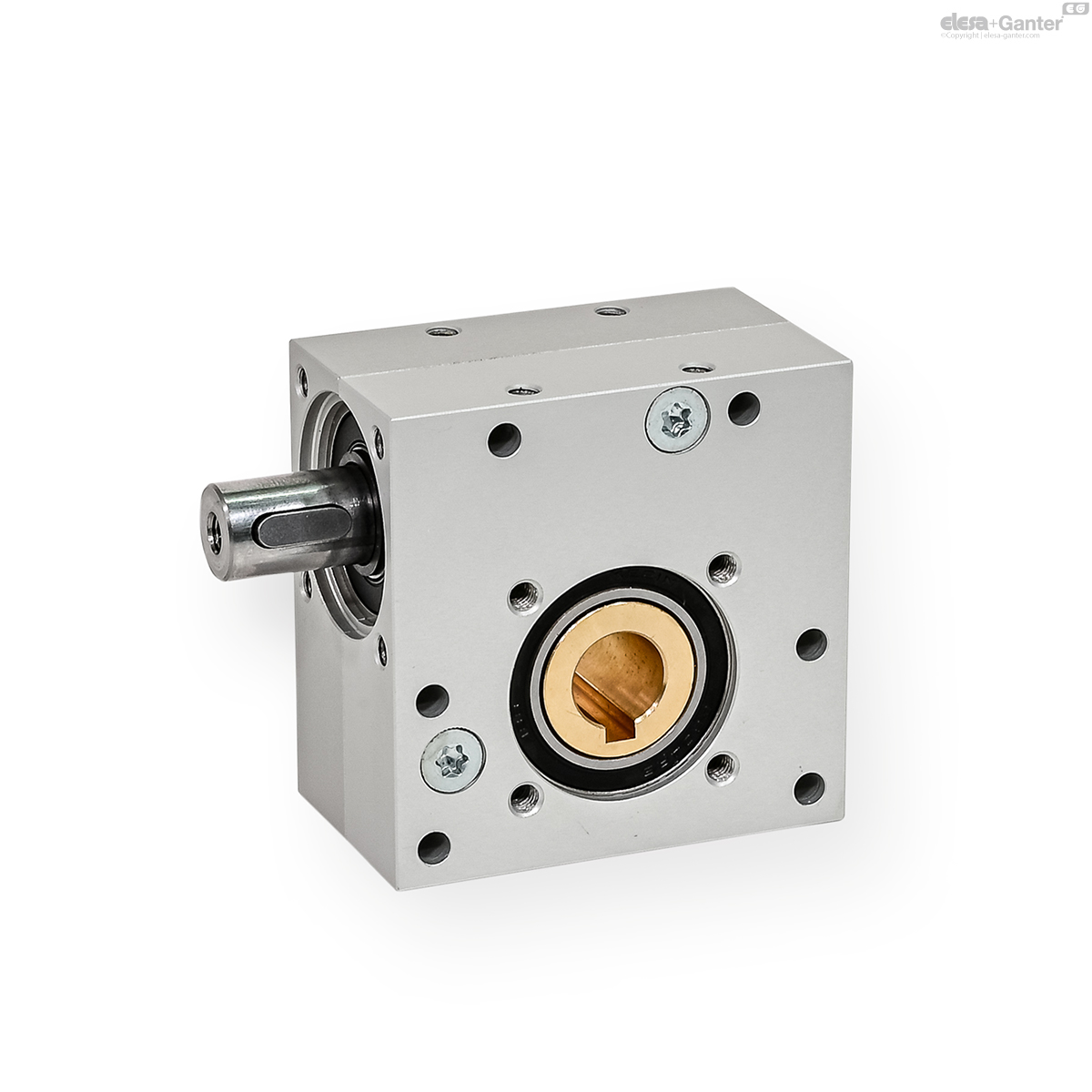
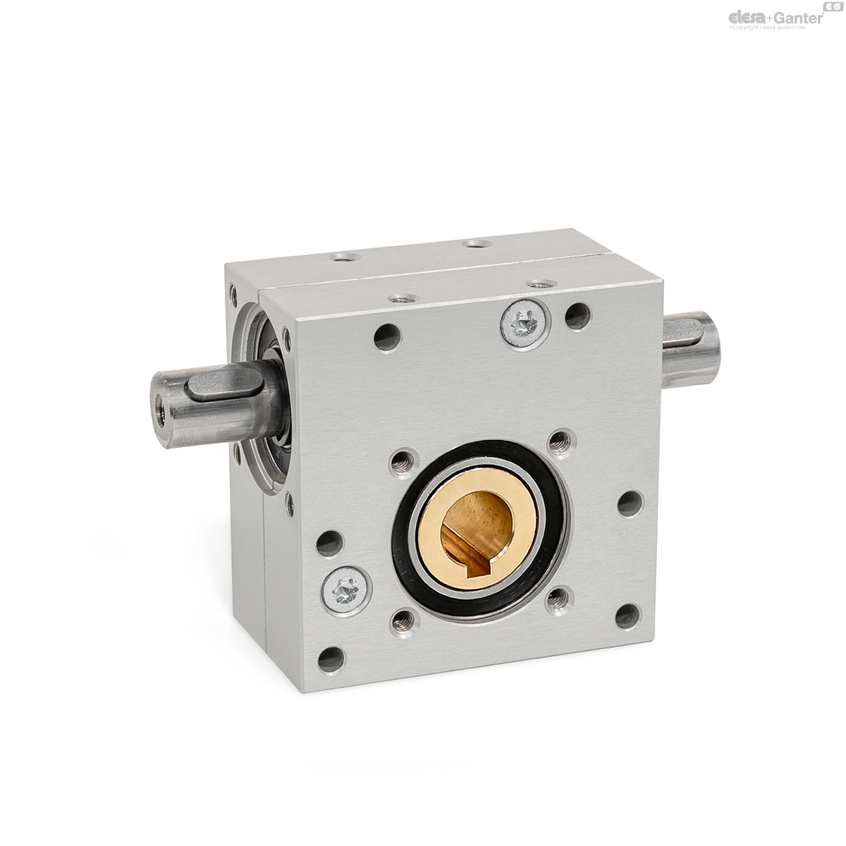
GN 3975
Worm Gear Reducers
Housing Aluminum
Description
Specification
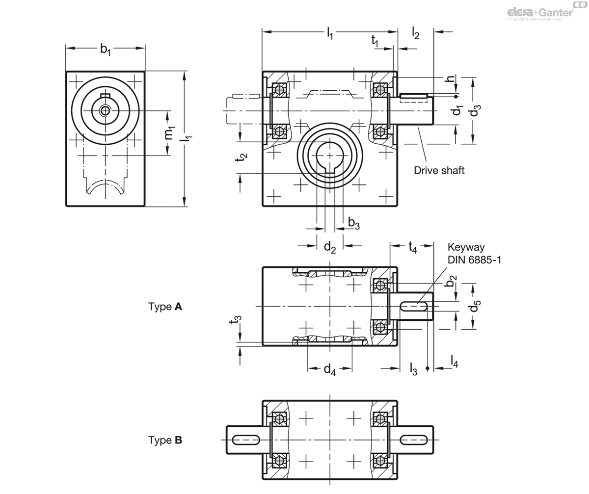
Types
- Type A: One-side drive
- Type B: Continuous drive
Housing
Aluminum
- Sealed to prevent dust entry
- Anodized, natural color AN
Worm screw
Steel
Worm wheel
Brass
Ball bearing
Steel
Sealed (sealing disks 2RS)
Operating temperature -20 °C to +60 °C
Information
Worm gear reducers GN 3975 can transmit high torque despite their very compact dimensions. They can readily be used for a multitude of applications, such as incline adjustments or to change the direction of shaft rotation.
The numerous fastening holes allow for simple mounting in any orientation or position. The parallel keys can take any angular positions.
Depending on the gear ratio, there may be no static self-braking between the worm screw and worm wheel, meaning that the worm wheel can be turned out of a resting state by a torque coming from the output end.
Technical information
- Keyways DIN 6885-1
- ISO-Fundamental Tolerances
Mechanical Features
| Circumferential backlash at the drive shaft | 1° ± 0.5° |
| Shaft direction of rotation | Any |
| Worm screw direction | Left |
| Life expectancy | 1.000 hours under full load at a rotational speed of 500 rpm, |
| assuming the gear box is operating for 20% of every 5 minutes (guide value) | |
| (1 minute of operation + 4 minutes break) at an ambient temperature of 20 °C | |
| Maintenance | Permanent lubrication with grease, maintenance-free |
| m1 | Gear ratio | Max. input torque in Nm* | Max. output torque in Nm* | Input side | Output side | Efficiency in % | Selfbraking | ||||||
| at 100 min-1 | at 500 min-1 | at 1000 min-1 | at 100 min-1 | at 500 min-1 | at 1000 min-1 | Max. radial force in N** | Max. axial force in N*** | Max. radial force in N** | Max. axial force in N*** | ||||
| 20 | 5 | 2.9 | 2.3 | 1.7 | 10 | 8 | 6 | 200 | 200 | 500 | 500 | 70 | - |
| 20 | 13 | 2.1 | 1.8 | 1.5 | 15 | 13 | 11 | 200 | 200 | 500 | 500 | 56 | - |
| 20 | 15 | 1.5 | 1.3 | 1 | 12 | 10 | 8 | 250 | 250 | 500 | 500 | 52 | - |
| 20 | 18 | 1.1 | 0.9 | 0.7 | 11 | 9 | 7 | 250 | 250 | 500 | 500 | 55 | - |
| 20 | 23 | 0.9 | 0.7 | 0.5 | 10 | 8 | 6 | 250 | 250 | 500 | 500 | 50 | - |
| 20 | 30 | 0.6 | 0.5 | 0.4 | 8.5 | 7 | 5.5 | 350 | 350 | 500 | 500 | 45 | - |
| 20 | 40 | 0.35 | 0.31 | 0.31 | 5.5 | 4.8 | 4 | 400 | 400 | 500 | 500 | 39 | x |
| 20 | 65 | 0.24 | 0.2 | 0.2 | 4.5 | 3.8 | 3 | 500 | 500 | 500 | 500 | 29 | x |
| 30 | 5 | 5.4 | 4.9 | 4.3 | 19 | 17 | 15 | 400 | 300 | 800 | 800 | 70 | - |
| 30 | 10 | 3.4 | 3.1 | 2.8 | 20 | 18 | 16 | 400 | 300 | 800 | 800 | 58 | - |
| 30 | 17 | 2.2 | 1.9 | 1.8 | 17 | 15 | 14 | 400 | 400 | 800 | 800 | 46 | - |
| 30 | 20 | 1.7 | 1.6 | 1.4 | 15 | 13.5 | 12 | 800 | 400 | 800 | 800 | 43 | - |
| 30 | 25 | 1.3 | 1.2 | 1.1 | 13.5 | 12 | 11 | 800 | 800 | 800 | 800 | 41 | - |
| 30 | 34 | 1.2 | 1.1 | 1 | 12 | 11 | 10 | 600 | 800 | 800 | 800 | 29 | - |
| 30 | 45 | 0.9 | 0.8 | 0.8 | 10.5 | 9.5 | 9 | 700 | 600 | 800 | 800 | 25 | - |
| 30 | 64 | 0.5 | 0.4 | 0.3 | 8.5 | 7.5 | 6 | 700 | 600 | 800 | 800 | 27 | x |
* Input side speed
** at axial force = 0
*** at radial force = 0
Assembly Instructions
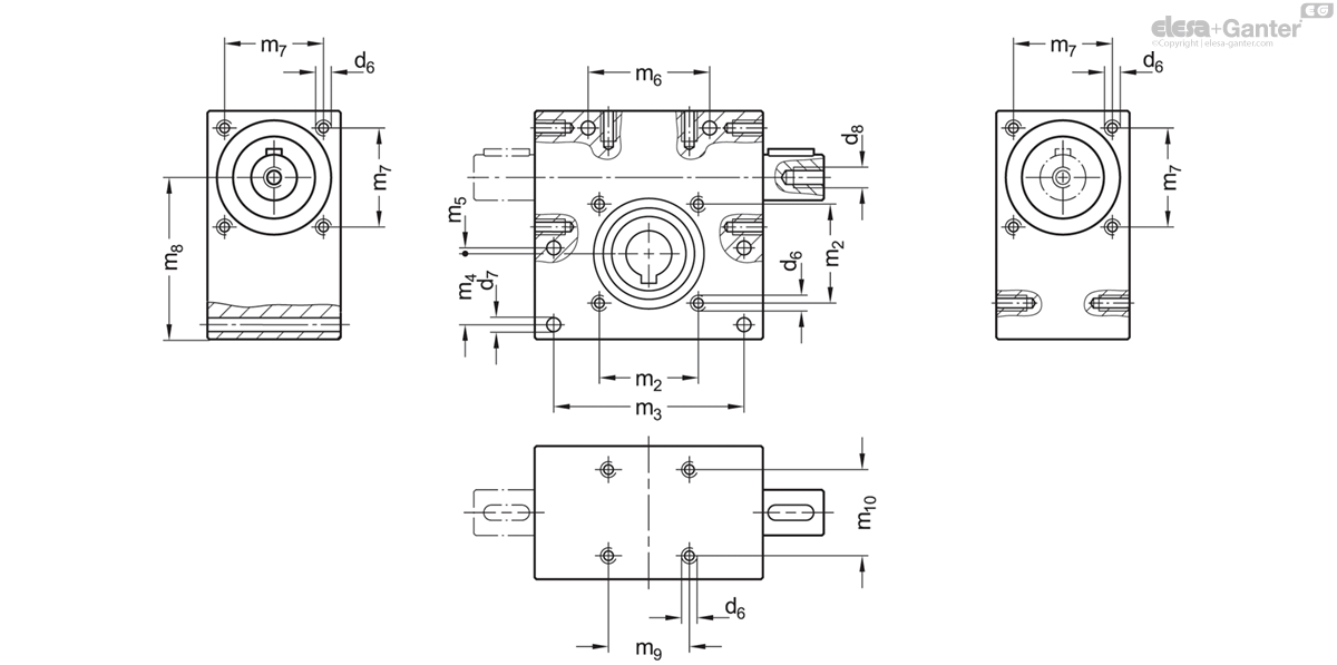
Do not exert any forces onto the housing or into the bearings during assembly. Use of the threaded holes d8 in the shaft is recommended. The use of a corresponding coupling is recommended to compensate for manufacturing-related shaft offsets and runout tolerances as well as for damping vibrations and shocks.
Application example
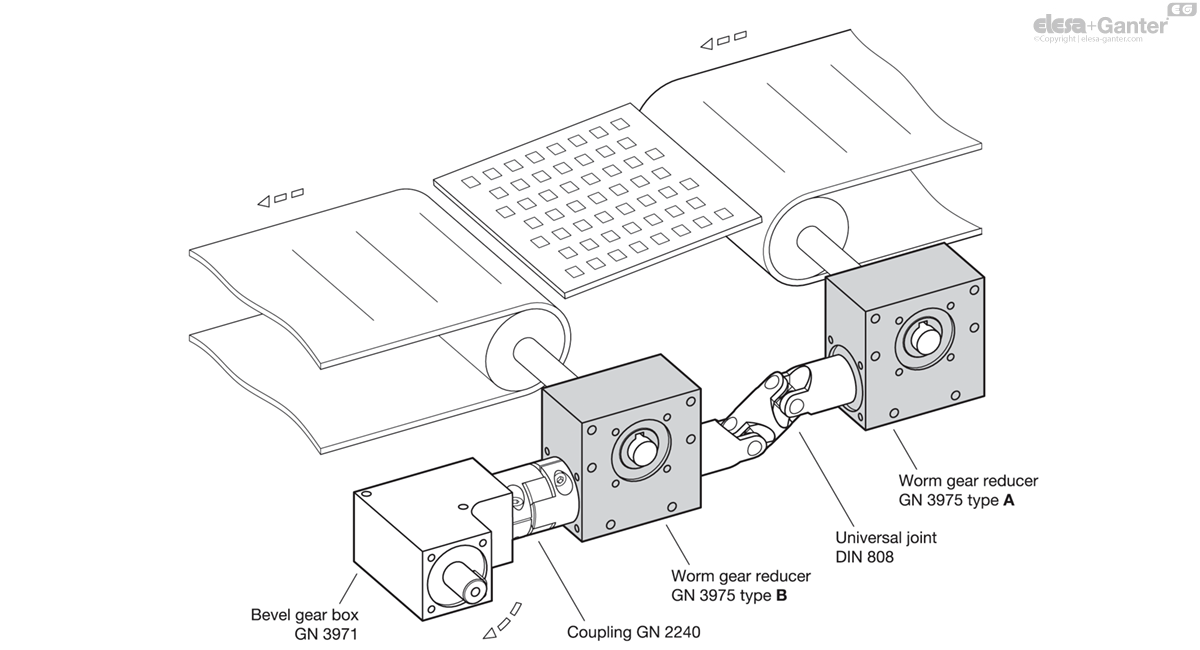
GN 3975-A
| m1 | d1 j6 | Gear ratio i |
b1 | b2 | b3 JS9 | d2 H7 | d3 | d4 | d5 | d6* | d7 | d8* | h | l1 | l2 | l3 | l4 | m2 | m3 | m4 | m5 | m6 | m7 | m8 | m9 | m10 | t1 | t2 | t3 | t4 | |||
|---|---|---|---|---|---|---|---|---|---|---|---|---|---|---|---|---|---|---|---|---|---|---|---|---|---|---|---|---|---|---|---|---|---|
| Code | Actions | ||||||||||||||||||||||||||||||||
| GN 3975-20-A-12-5-AN | 20 | 12 | 5 | 35 | 4 | 4 | 12 | 30 | 20 | 27.4 | M 4 | 4.2 | M 5 | 1.5 | 60 | 16 | 12 | 3 | 26 | 50 | 17.5 | 1.5 | 31 | 26 | 42.5 | 22.5 | 26 | 2 | 13.8 | 1.6 | 18.3 | 434 |
|
| GN 3975-20-A-12-13-AN | 20 | 12 | 13 | 35 | 4 | 4 | 12 | 30 | 20 | 27.4 | M 4 | 4.2 | M 5 | 1.5 | 60 | 16 | 12 | 3 | 26 | 50 | 17.5 | 1.5 | 31 | 26 | 42.5 | 22.5 | 26 | 2 | 13.8 | 1.6 | 18.3 | 422 |
|
| GN 3975-20-A-12-15-AN | 20 | 12 | 15 | 35 | 4 | 4 | 12 | 30 | 20 | 27.4 | M 4 | 4.2 | M 5 | 1.5 | 60 | 16 | 12 | 3 | 26 | 50 | 17.5 | 1.5 | 31 | 26 | 42.5 | 22.5 | 26 | 2 | 13.8 | 1.6 | 18.3 | 425 |
|
| GN 3975-20-A-12-18-AN | 20 | 12 | 18 | 35 | 4 | 4 | 12 | 30 | 20 | 27.4 | M 4 | 4.2 | M 5 | 1.5 | 60 | 16 | 12 | 3 | 26 | 50 | 17.5 | 1.5 | 31 | 26 | 42.5 | 22.5 | 26 | 2 | 13.8 | 1.6 | 18.3 | 426 |
|
| GN 3975-20-A-12-23-AN | 20 | 12 | 23 | 35 | 4 | 4 | 12 | 30 | 20 | 27.4 | M 4 | 4.2 | M 5 | 1.5 | 60 | 16 | 12 | 3 | 26 | 50 | 17.5 | 1.5 | 31 | 26 | 42.5 | 22.5 | 26 | 2 | 13.8 | 1.6 | 18.3 | 428 |
|
| GN 3975-20-A-12-30-AN | 20 | 12 | 30 | 35 | 4 | 4 | 12 | 30 | 20 | 27.4 | M 4 | 4.2 | M 5 | 1.5 | 60 | 16 | 12 | 3 | 26 | 50 | 17.5 | 1.5 | 31 | 26 | 42.5 | 22.5 | 26 | 2 | 13.8 | 1.6 | 18.3 | 438 |
|
| GN 3975-20-A-12-40-AN | 20 | 12 | 40 | 35 | 4 | 4 | 12 | 30 | 20 | 27.4 | M 4 | 4.2 | M 5 | 1.5 | 60 | 16 | 12 | 3 | 26 | 50 | 17.5 | 1.5 | 31 | 26 | 42.5 | 22.5 | 26 | 2 | 13.8 | 1.6 | 18.3 | 426 |
|
| GN 3975-20-A-12-65-AN | 20 | 12 | 65 | 35 | 4 | 4 | 12 | 30 | 20 | 27.4 | M 4 | 4.2 | M 5 | 1.5 | 60 | 16 | 12 | 3 | 26 | 50 | 17.5 | 1.5 | 31 | 26 | 42.5 | 22.5 | 26 | 2 | 13.8 | 1.6 | 18.3 | 432 |
|
| GN 3975-30-A-12-5-AN | 30 | 12 | 5 | 40 | 4 | 5 | 14 | 30 | 25 | 27.4 | M 5 | 5.5 | M 5 | 1.5 | 80 | 16 | 12 | 3 | 40 | 60 | 20 | 10 | 15 | 26 | 57.5 | 30 | 30 | 4 | 16.3 | 2 | 20.5 | 867 |
|
| GN 3975-30-A-12-10-AN | 30 | 12 | 10 | 40 | 4 | 5 | 14 | 30 | 25 | 27.4 | M 5 | 5.5 | M 5 | 1.5 | 80 | 16 | 12 | 3 | 40 | 60 | 20 | 10 | 15 | 26 | 57.5 | 30 | 30 | 4 | 16.3 | 2 | 20.5 | 882 |
|
| GN 3975-30-A-12-17-AN | 30 | 12 | 17 | 40 | 4 | 5 | 14 | 30 | 25 | 27.4 | M 5 | 5.5 | M 5 | 1.5 | 80 | 16 | 12 | 3 | 40 | 60 | 20 | 10 | 15 | 26 | 57.5 | 30 | 30 | 4 | 16.3 | 2 | 20.5 | 863 |
|
| GN 3975-30-A-12-20-AN | 30 | 12 | 20 | 40 | 4 | 5 | 14 | 30 | 25 | 27.4 | M 5 | 5.5 | M 5 | 1.5 | 80 | 16 | 12 | 3 | 40 | 60 | 20 | 10 | 15 | 26 | 57.5 | 30 | 30 | 4 | 16.3 | 2 | 20.5 | 861 |
|
| GN 3975-30-A-12-25-AN | 30 | 12 | 25 | 40 | 4 | 5 | 14 | 30 | 25 | 27.4 | M 5 | 5.5 | M 5 | 1.5 | 80 | 16 | 12 | 3 | 40 | 60 | 20 | 10 | 15 | 26 | 57.5 | 30 | 30 | 4 | 16.3 | 2 | 20.5 | 869 |
|
| GN 3975-30-A-12-34-AN | 30 | 12 | 34 | 40 | 4 | 5 | 14 | 30 | 25 | 27.4 | M 5 | 5.5 | M 5 | 1.5 | 80 | 16 | 12 | 3 | 40 | 60 | 20 | 10 | 15 | 26 | 57.5 | 30 | 30 | 4 | 16.3 | 2 | 20.5 | 865 |
|
| GN 3975-30-A-12-45-AN | 30 | 12 | 45 | 40 | 4 | 5 | 14 | 30 | 25 | 27.4 | M 5 | 5.5 | M 5 | 1.5 | 80 | 16 | 12 | 3 | 40 | 60 | 20 | 10 | 15 | 26 | 57.5 | 30 | 30 | 4 | 16.3 | 2 | 20.5 | 870 |
|
| GN 3975-30-A-12-64-AN | 30 | 12 | 64 | 40 | 4 | 5 | 14 | 30 | 25 | 27.4 | M 5 | 5.5 | M 5 | 1.5 | 80 | 16 | 12 | 3 | 40 | 60 | 20 | 10 | 15 | 26 | 57.5 | 30 | 30 | 4 | 16.3 | 2 | 20.5 | 881 |
|

Enquiry Now
To allow us to respond to your enquiry promptly, please provide all required information.
Related Products
-
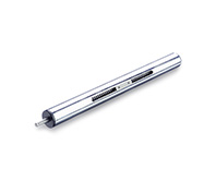 GN 291Linear ActuatorsSteel / Stainless Steel, with Right or Left Hand ThreadView Product
 -
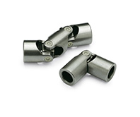 DIN 808Universal Joints with Friction Bearing / Needle BearingSteel / Stainless Steel, Single or DoubleView Product
 -
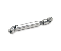 GN 808.2Universal Joint Shafts with Friction Bearingwith Longitudinal CompensationView Product
 -
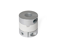 GN 2242Oldham couplingswith clamping hubView Product
 -
 GN 2240Elastomer jaw couplingswith clamping hubView Product
 -
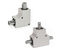 GN 3971Bevel Gear BoxesHousing AluminumView Product
 -
 GN 923Disk HandwheelsAluminum, Powder CoatedView Product
 -
 ZGDToothed jointsTechnopolymerView Product
 -
ZCLSpur GearsTechnopolymer, pressure angle 20°View Product
-
NSFLead screw nutsTrapezoidal thread, technopolymerView Product