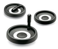
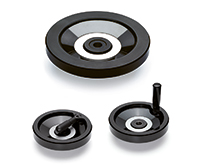
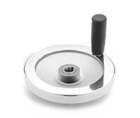
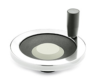
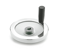
GN 327
Safety handwheels
Aluminium, fixed bearing flange
Description
Specification
Types
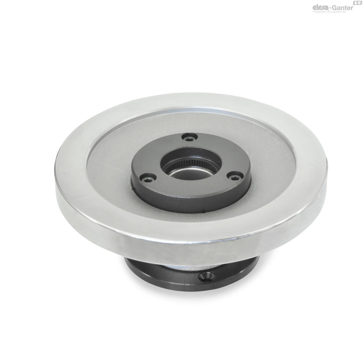
- Type A: without handle
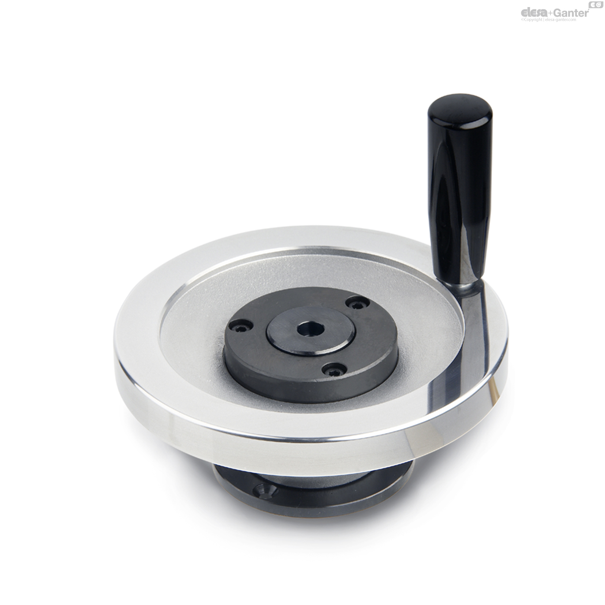
- Type D: with revolving handle
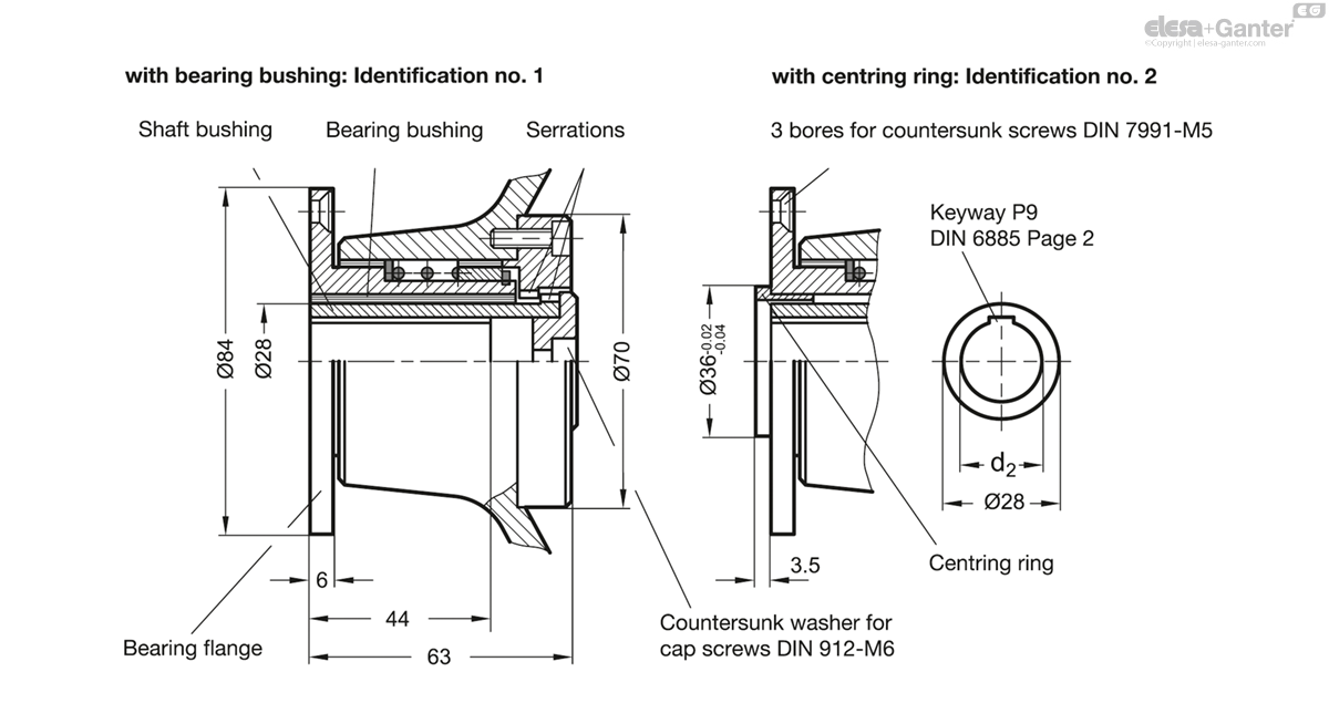
Identification no.
- Version 1: with bearing bush
- Version 2: with centring ring
Handwheel body
Aluminium
Rim turned and polished
Coupling elements
- Steel, nitrided
- Bearing surface ground and / or PTFE-coated
- Bearing flange blackened
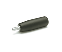
Cylindrical Revolving handles GN 598
- Plastic, technopolymer, black matt
- Spindle steel, zinc plated, blue passivated
Information
Safety handwheels GN 327 feature the ultimate in health and safety at work standards because the handwheel, if disengaged, is mounted on a fixed component, the bearing flange. The wheel is fully disengaged from the rotating shaft.
The bearing flange can also accept the bearing of the shaft via the bearing bushing (code No. 1). This bearing bushing is a dry bearing (DU bushing). Normally, the shaft has a separate bearing and the bearing bushing serves to center the bearing flange.
Centering can also be effected by a centering ring (code No. 2) if the appropriate bore hole has been made at the machine side. In this case there is no need for the bearing bushes and no bearing friction (heating) will occur.
- Instructions for safety handwheels
- Operating instructions for safety handwheels
Technical information
- Keyway P9 DIN 6885
- ISO-Fundamental Tolerances
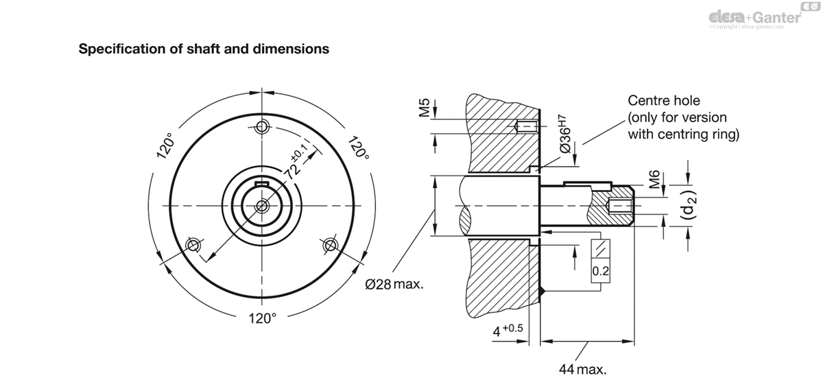
Assembly instructions
Shaft bush and countershaft pulley are delivered in two separate components. Before assembly, make sure that the shaft bush can be pushed smoothly and free-moving over the shaft.
Proper function is guaranteed only if:
- shaft bush and bearing surface are level with each other
- the shaft axis lies at a right angle to the bearing surface on the machine side.
Design with bearing bush (Mode 1)
Push the handwheel and the shaft bush at the same time over the shaft, bolt down the bearing flange, and fix the shaft bush axially with the countershaft pulley
Design with centring ring (Mode 2)
The handwheel can be bolted at once through the centring ring above the bearing flange. Then push the shaft bush onto the shaft and fix it axially with the countershaft pulley.
GN 327-A
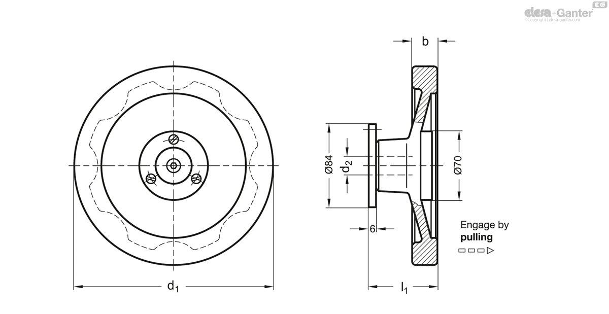
| d1 | d2 H7 | b | l1 | |||
|---|---|---|---|---|---|---|
| Code | Actions | |||||
| GN 327-160-K14-A-1 | 160 | K 14 | 18 | 66 | 1706 |
|
| GN 327-160-K14-A-2 | 160 | K 14 | 18 | 66 | 1702 |
|
| GN 327-160-K16-A-1 | 160 | K 16 | 18 | 66 | 1690 |
|
| GN 327-160-K16-A-2 | 160 | K 16 | 18 | 66 | 1686 |
|
| GN 327-160-K18-A-1 | 160 | K 18 | 18 | 66 | 1670 |
|
| GN 327-160-K18-A-2 | 160 | K 18 | 18 | 66 | 1666 |
|
| GN 327-160-K20-A-1 | 160 | K 20 | 18 | 66 | 1649 |
|
| GN 327-160-K20-A-2 | 160 | K 20 | 18 | 66 | 1800 |
|
| GN 327-200-K14-A-1 | 200 | K 14 | 20.5 | 68 | 2047 |
|
| GN 327-200-K14-A-2 | 200 | K 14 | 20.5 | 68 | 2043 |
|
| GN 327-200-K16-A-1 | 200 | K 16 | 20.5 | 68 | 2031 |
|
| GN 327-200-K16-A-2 | 200 | K 16 | 20.5 | 68 | 2027 |
|
| GN 327-200-K18-A-1 | 200 | K 18 | 20.5 | 68 | 2011 |
|
| GN 327-200-K18-A-2 | 200 | K 18 | 20.5 | 68 | 2007 |
|
| GN 327-200-K20-A-1 | 200 | K 20 | 20.5 | 68 | 1990 |
|
| GN 327-200-K20-A-2 | 200 | K 20 | 20.5 | 68 | 2000 |
|

Enquiry Now
To allow us to respond to your enquiry promptly, please provide all required information.
Related Products
-
 GN 598Revolving HandlesSteel, Spindle SteelView Product
 -
 GN 321.4Safety handwheelsfriction bearingView Product
 -
 VDT.Solid handwheelsTechnopolymerView Product
 -
VDN.FPSolid handwheelsDuroplast, steel hubView Product
-
 GN 321.6Safety HandwheelsAluminum, with Needle BearingsView Product
 -
VDS.Solid handwheelsTechnopolymerView Product
-
 GN 321.5Safety HandwheelsAluminum, with Needle BearingView Product