

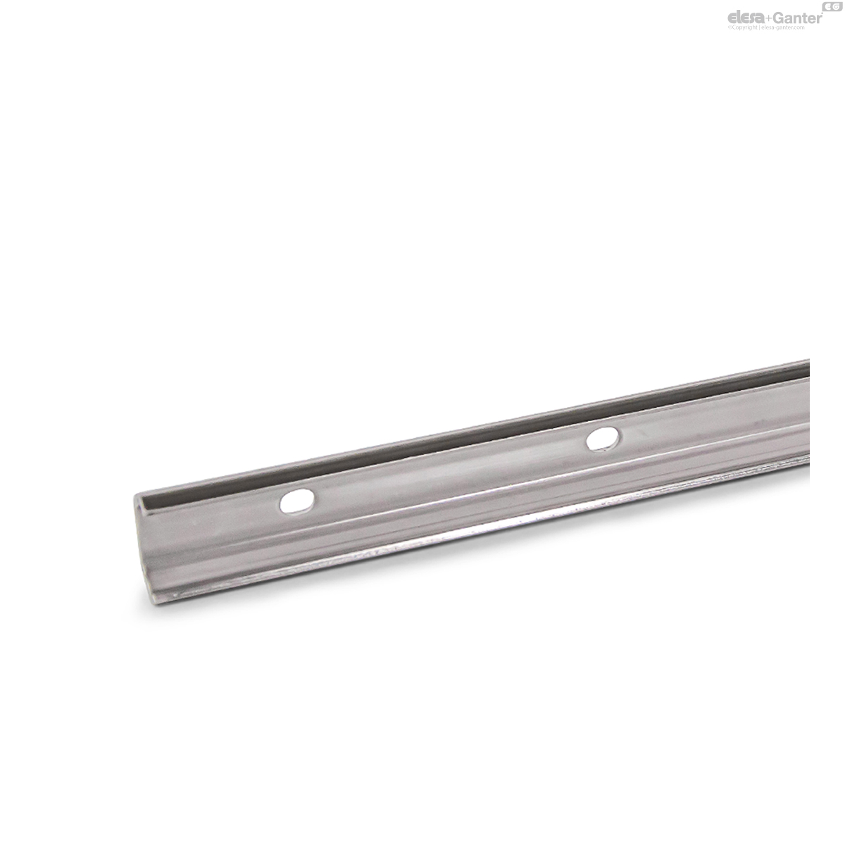
GN 2492
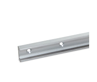
Stainless Steel Cam Roller Linear Guide Rails
for Stainless Steel Linear Guide Rail Systems
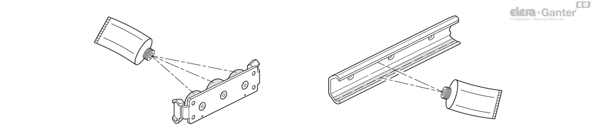
Description
Specification
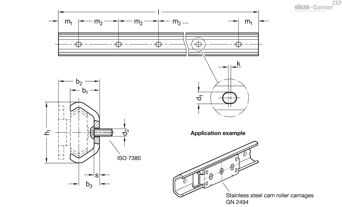
Type
- Type XL: Fixed bearing guide rail with elongated holes
Stainless steel AISI 316L
Plain
Information
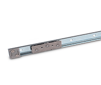
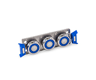
Stainless steel cam roller linear guide rails GN 2492 can be combined with stainless steel cam roller carriages GN 2494 or stainless steel cam rollers GN 2496 to build linear guide rail systems.
These space-saving units are used for example in the machine and jig building industry, in transportation and building services equipment for supporting sliding doors, or to enable the linear movement of production and plant equipment. The material can also be used in particularly aggressive environments that can be found, for example, in the chemical, pharmaceutical, medical or food processing industries.
Linear guide rail systems are generally installed in pairs, with a horizontal alignment, either vertically (as shown) or perpendicularly. The rails can be installed on either the left or the right side of the application.
Accessory
- Stainless Steel Cam Roller Carriages GN 2494
- Stainless Steel Cam Rollers GN 2496
On request
- Other available guide rail lengths
- for h1 = 30: up to 4000 mm
- for h1 = 45: up to 5200 mm
- Different mounting hole distance m1 / m2
Technical information
- Stainless Steel characteristics
General installation information
The following installation information should be taken into account in the use and assembly of stainless steel linear guide rail systems.
This ensures smooth running, quiet operation, low wear, and proper function over prolonged use.
- Stainless steel linear guide rail systems are normally installed in pairs. The surrounding structure should have adequate stability, e.g. to minimize geometric errors caused by elastic deformation.
- The mounting surfaces of the linear guide rail systems (guide rails and cam roller carriages) must be level, parallel, and at right angles as well as correctly situated relative to each other. The linear limit of the runner is established by external stop elements. If several stops are used, they should be reached at the same time.
- Fastening holes should be applied in such a way that excludes twisting or warping of the stainless steel guide rails during mounting.
- After the linear guide rail systems are mounted, they must be checked to ensure smooth running. If something is wrong such as sticking or warping, the cause has to be determined and appropriately eliminated.
Mounting holes, fastening screws
During assembly, all mounting slots in the guide rail and the fastening thread on the cam roller carriage must be used. This ensures that the forces resulting from the maximum load FR / FA are reliably transferred to the surrounding structure. Failure to use fastening screws reduces the load capacity accordingly.
Various screws with the appropriate threads can be used for mounting the cam roller carriages. Observe the maximum thread tightening depth „t“. In contrast, assemble the rail with ISO 7380 screws (screws with a flat semicircular head) to avoid collisions with the cam roller carriage. Screws with a head height that is the same or less are also permissible. It is generally recommended to use stainless steel screws of property class A2 or A4-70 or higher under consideration of the specified tightening torque.
Installation instructions
Stainless steel linear guide rail systems are made up of stainless steel cam roller linear guide rails GN 2492 and stainless steel cam roller carriages GN 2494. All required components are provided unassembled in separate packages.
When delivered, the play between cam roller carriage and rail is not preset. During assembly, set the cam roller carriage as follows:
1. Make sure that the raceways and guide rollers are clean.
2. Loosen the fixing screw of the central adjustable eccentric guide roller slightly and insert the cam roller carriage into the guide rail without the wipers (see steps 4 and 6).
3. Position the roller carriage at one end of the guide rail.
4. Insert the open-end wrench between the eccentric roller and the cam roller carriage. The two centering holes on the left and right of the cam roller carriage mark the position of the running side for the two concentric and supporting rollers.
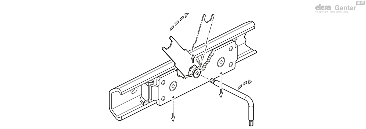
5. Turning the wrench clockwise presses the guide roller against the support raceway of the rail so that there is no play for the roller carriage. Overtightening will increase friction and reduce the service life of the item.
6. While holding the bearing pivot of the eccentric guide roller in place with the wrench, tighten the fixing screw moderately. The precise torque will be checked later.
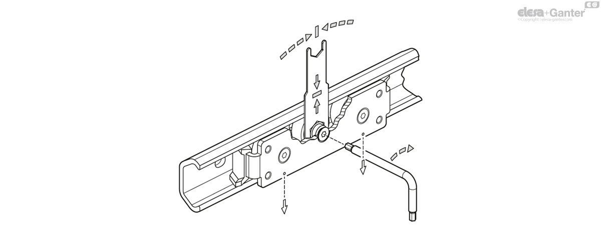
7. Move the cam roller carriage in the guide rail and make sure that the play or slight preload is consistent across the entire length of the rail. The cam roller carriage should move easily without being overly loose or tight. Adjust if necessary.
8. Tighten the fixing screw using the torque specified in the table (observe construction height h1). Use the open-end wrench to hold the eccentric guide roller at its final angle to prevent accidental adjustments. Adhesive can also be used to fix the screw in position.
| h1 (construction height) | Torque |
| 30 | 6 Nm |
| 45 | 10 Nm |
9. Insert the wipers. Take the roller carriage out of the rail and reinsert it to check where the wipers will go. The wipers will self-align during use.
10. Spare parts:
- Stainless Steel Cam Rollers GN 2496
- Wipers GN 2498
- Open-End Wrench GN 2424.1-13-15
Travel speed
The maximum travel speed of the stainless steel linear guide rail systems is 1.5 m/s. The acceleration may be up to 2 m/s2. If end stops are used, the speed should be significantly reduced before reaching the stop to avoid damage.
Operational temperatures
The temperature of use of the linear guide rails is -20 °C to 100 °C. The temperature range is dictated by the wiper material. If they are not needed, the range extends from -40 °C to 100 °C (briefly 120°) since the material of the sealing discs of the cam rollers then sets the temperature range.
Load capacity
The maximum load capacity of a linear guide rail system corresponds to the use of two cam roller carriages and is limited by the stability of the guide rail. The total width as well as the stiffness of the application also play a role and can negatively impact the load capacity and wear properties.
To reach the indicated nominal load FR, install the cam roller carriage so that the load is applied to the side with the greatest number of rollers. To prevent mix-ups, this is marked with two notches on the base body of the carriage.
The total load FG of the application must be transmitted to the cam roller carriages as centrally as possible. Sudden impacts and jolts as well as strong vibrations acting on the linear guide rail systems are to be avoided. The application or absorption of torque forces in the MX and MZ directions via to the cam roller carriages is not intended.
If higher loads are to be moved, this can be accomplished by using an additional support structure (in the FR direction) on the outside of the guide rail which allows additional cam roller carriages to be used. The support keeps the rail from spreading or slipping. However, functioning should be checked in a test set-up.

| h1 (construction height) | FR per cam roller carriage in N | FG resulting in N | MY per cam roller carriage in Nm | |
| with 2 cam roller carriages | with 4 cam roller carriages | |||
| 30 | 840 | 1680 | 3360 | 14 |
| 45 | 1690 | 3380 | 6760 | 35 |
Lubrication and maintenance
The cam roller linear guide rails and cam roller carriages should be lightly lubricated on the running surfaces and with high performance roller bearing grease before initial use. The grease should be distributed evenly over the entire length of the rail using a paintbrush. In normal environments, Shell Gadus S2 V220 or Klüberplex BE 31-222, for example, can be used as a lubricant. In areas of application such as the food and pharmaceutical industry, use lubricants approved by the FDA. Examples are Klüberfood NH1 94-301 or Klübersynth UH1 14-151.
After 50 km, six months, or equivalent soiling or discoloration of the lubricant, the rails and cam roller carriages should be cleaned with a clean cloth and re-lubricated. If potential soiling is greater, the maintenance intervals should be shorter. Prevent soiling by providing suitable covering or optimum placement of the linear guide rail systems.
Installation position
Stainless steel linear guide rail systems are preferably installed vertically, in pairs, with a horizontal alignment. This results in the highest possible stability and torsional stiffness in the smallest installation space. The running properties are optimal in this arrangement, and wear is reduced to a minimum.
In contrast to telescopic slides, linear guide rail systems can be used in a vertical orientation because no cage slip occurs since the design does not include a ball cage. It is only necessary to consider the direction in which the load acts so that the cam roller carriages can be inserted correctly into the guide rail.
The horizontal installation of the rail (lying down) is likewise possible with certain restrictions. The maximum load in this case is specified as the nominal load FA. Due to the unfavorable rail cross-section, larger forces can be expected to widen the rail, which may lead to a collision between the cam roller carriages and the heads of the mounting screws. In case of doubt, check the function under load in a test set-up.
| favorable | vertically, on both sides | |
| acceptable | vertically shifted, on both sides | vertically inclined, on both sides |
| unfavorable | vertically, on one side | horizontally, on one side |
Additional information on use
- For applications in which there is a long travel path, rails with an overall length of 5200 mm are available upon request. Do not sequentially arrange several cam roller linear guide rails to achieve a longer travel path since the set play or preloading of the cam roller carriages cannot be kept constant over several rails.
- The guide rails can be cut to any length, if necessary. When sawing, care should be taken to not deform the profile cross-section. The use of a clamp is recommended. After cutting, the cut surfaces must be deburred and cleaned before lubricating the running surfaces.
GN 2492
| h1 Nominal size |
h1 Actual size | l +2/-4 | m1 +1/-2 | b1 | b2 | b3 | d1 | d2 | k | m2 | s | |||
|---|---|---|---|---|---|---|---|---|---|---|---|---|---|---|
| Code | Actions | |||||||||||||
| GN 2492-30-240-40-XL | 30 | 29.5 | 240 | 40 | 15 | 20.5 | 10 | 6.4 | M 5 | 2 | 80 | 2.5 | 210 |
|
| GN 2492-30-320-40-XL | 30 | 29.5 | 320 | 40 | 15 | 20.5 | 10 | 6.4 | M 5 | 2 | 80 | 2.5 | 280 |
|
| GN 2492-30-400-40-XL | 30 | 29.5 | 400 | 40 | 15 | 20.5 | 10 | 6.4 | M 5 | 2 | 80 | 2.5 | 350 |
|
| GN 2492-30-480-40-XL | 30 | 29.5 | 480 | 40 | 15 | 20.5 | 10 | 6.4 | M 5 | 2 | 80 | 2.5 | 430 |
|
| GN 2492-30-560-40-XL | 30 | 29.5 | 560 | 40 | 15 | 20.5 | 10 | 6.4 | M 5 | 2 | 80 | 2.5 | 500 |
|
| GN 2492-30-640-40-XL | 30 | 29.5 | 640 | 40 | 15 | 20.5 | 10 | 6.4 | M 5 | 2 | 80 | 2.5 | 570 |
|
| GN 2492-30-720-40-XL | 30 | 29.5 | 720 | 40 | 15 | 20.5 | 10 | 6.4 | M 5 | 2 | 80 | 2.5 | 640 |
|
| GN 2492-30-800-40-XL | 30 | 29.5 | 800 | 40 | 15 | 20.5 | 10 | 6.4 | M 5 | 2 | 80 | 2.5 | 710 |
|
| GN 2492-30-880-40-XL | 30 | 29.5 | 880 | 40 | 15 | 20.5 | 10 | 6.4 | M 5 | 2 | 80 | 2.5 | 780 |
|
| GN 2492-30-960-40-XL | 30 | 29.5 | 960 | 40 | 15 | 20.5 | 10 | 6.4 | M 5 | 2 | 80 | 2.5 | 850 |
|
| GN 2492-30-1040-40-XL | 30 | 29.5 | 1040 | 40 | 15 | 20.5 | 10 | 6.4 | M 5 | 2 | 80 | 2.5 | 920 |
|
| GN 2492-30-1200-40-XL | 30 | 29.5 | 1200 | 40 | 15 | 20.5 | 10 | 6.4 | M 5 | 2 | 80 | 2.5 | 1060 |
|
| GN 2492-30-1360-40-XL | 30 | 29.5 | 1360 | 40 | 15 | 20.5 | 10 | 6.4 | M 5 | 2 | 80 | 2.5 | 1210 |
|
| GN 2492-30-1520-40-XL | 30 | 29.5 | 1520 | 40 | 15 | 20.5 | 10 | 6.4 | M 5 | 2 | 80 | 2.5 | 1350 |
|
| GN 2492-30-1760-40-XL | 30 | 29.5 | 1760 | 40 | 15 | 20.5 | 10 | 6.4 | M 5 | 2 | 80 | 2.5 | 1560 |
|
| GN 2492-30-2000-40-XL | 30 | 29.5 | 2000 | 40 | 15 | 20.5 | 10 | 6.4 | M 5 | 2 | 80 | 2.5 | 1770 |
|
| GN 2492-30-2240-40-XL | 30 | 29.5 | 2240 | 40 | 15 | 20.5 | 10 | 6.4 | M 5 | 2 | 80 | 2.5 | 1990 |
|
| GN 2492-30-2480-40-XL | 30 | 29.5 | 2480 | 40 | 15 | 20.5 | 10 | 6.4 | M 5 | 2 | 80 | 2.5 | 2200 |
|
| GN 2492-45-240-40-XL | 45 | 45.7 | 240 | 40 | 22 | 30.5 | 15.5 | 9 | M 8 | 2 | 80 | 4 | 540 |
|
| GN 2492-45-320-40-XL | 45 | 45.7 | 320 | 40 | 22 | 30.5 | 15.5 | 9 | M 8 | 2 | 80 | 4 | 710 |
|
| GN 2492-45-400-40-XL | 45 | 45.7 | 400 | 40 | 22 | 30.5 | 15.5 | 9 | M 8 | 2 | 80 | 4 | 890 |
|
| GN 2492-45-480-40-XL | 45 | 45.7 | 480 | 40 | 22 | 30.5 | 15.5 | 9 | M 8 | 2 | 80 | 4 | 1070 |
|
| GN 2492-45-560-40-XL | 45 | 45.7 | 560 | 40 | 22 | 30.5 | 15.5 | 9 | M 8 | 2 | 80 | 4 | 1250 |
|
| GN 2492-45-640-40-XL | 45 | 45.7 | 640 | 40 | 22 | 30.5 | 15.5 | 9 | M 8 | 2 | 80 | 4 | 1430 |
|
| GN 2492-45-720-40-XL | 45 | 45.7 | 720 | 40 | 22 | 30.5 | 15.5 | 9 | M 8 | 2 | 80 | 4 | 1610 |
|
| GN 2492-45-800-40-XL | 45 | 45.7 | 800 | 40 | 22 | 30.5 | 15.5 | 9 | M 8 | 2 | 80 | 4 | 1780 |
|
| GN 2492-45-880-40-XL | 45 | 45.7 | 880 | 40 | 22 | 30.5 | 15.5 | 9 | M 8 | 2 | 80 | 4 | 1960 |
|
| GN 2492-45-960-40-XL | 45 | 45.7 | 960 | 40 | 22 | 30.5 | 15.5 | 9 | M 8 | 2 | 80 | 4 | 2140 |
|
| GN 2492-45-1040-40-XL | 45 | 45.7 | 1040 | 40 | 22 | 30.5 | 15.5 | 9 | M 8 | 2 | 80 | 4 | 2320 |
|
| GN 2492-45-1200-40-XL | 45 | 45.7 | 1200 | 40 | 22 | 30.5 | 15.5 | 9 | M 8 | 2 | 80 | 4 | 2680 |
|
| GN 2492-45-1360-40-XL | 45 | 45.7 | 1360 | 40 | 22 | 30.5 | 15.5 | 9 | M 8 | 2 | 80 | 4 | 3030 |
|
| GN 2492-45-1520-40-XL | 45 | 45.7 | 1520 | 40 | 22 | 30.5 | 15.5 | 9 | M 8 | 2 | 80 | 4 | 3390 |
|
| GN 2492-45-1760-40-XL | 45 | 45.7 | 1760 | 40 | 22 | 30.5 | 15.5 | 9 | M 8 | 2 | 80 | 4 | 3920 |
|
| GN 2492-45-2000-40-XL | 45 | 45.7 | 2000 | 40 | 22 | 30.5 | 15.5 | 9 | M 8 | 2 | 80 | 4 | 4460 |
|
| GN 2492-45-2240-40-XL | 45 | 45.7 | 2240 | 40 | 22 | 30.5 | 15.5 | 9 | M 8 | 2 | 80 | 4 | 5000 |
|
| GN 2492-45-2480-40-XL | 45 | 45.7 | 2480 | 40 | 22 | 30.5 | 15.5 | 9 | M 8 | 2 | 80 | 4 | 5530 |
|

Enquiry Now
To allow us to respond to your enquiry promptly, please provide all required information.
Related Products
-
 GN 2498Wipersfor Stainless Steel Cam Roller Linear Guide Rails GN 2492View Product
 -
 GN 1490Linear Guide Rail SystemsSteel / Stainless Steel, with Inside Traversal DistanceView Product
 -
 GN 2496Stainless Steel Cam Rollersfor Stainless Steel Cam Roller Linear Guide Rails GN 2492View Product
 -
 GN 2494Stainless Steel Cam Roller Carriagesfor Stainless Steel Cam Roller Linear Guide Rails GN 2492View Product
 -
 GN 2422Cam Roller Linear Guide Railsfor Linear Guide Rail Systems, C-ProfileView Product

