

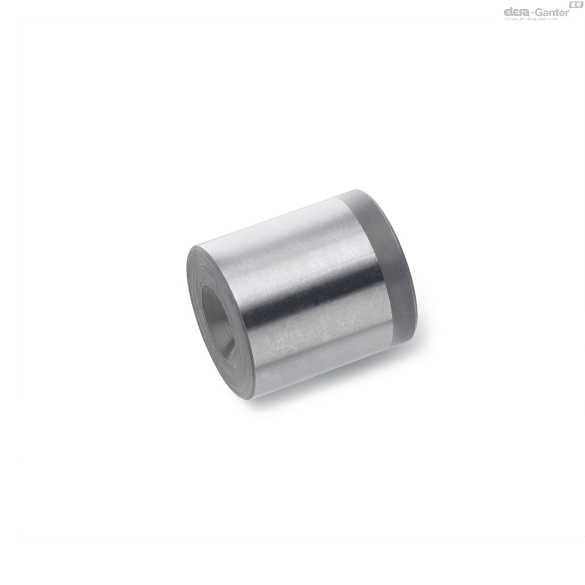
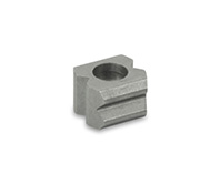
GN 249.1
Ball buttons
for spring plungers
Description
Specification
Steel
hardened and ground
Information
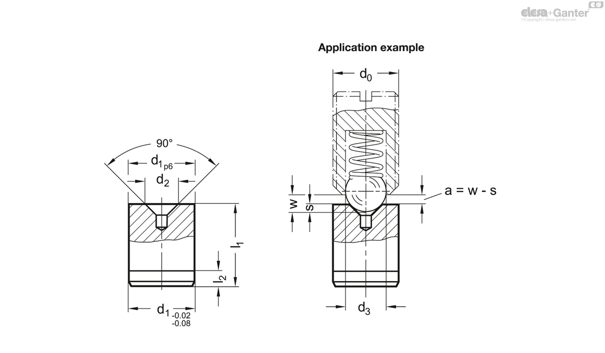
Ball buttons GN 249.1 are mainly used with spring plungers when low wear and exact positioning are needed.
To achieve optimal locking of the spring plungers, the maximum distance a between the ball button and the spring plunger should not be exceeded. The maximum distance a is calculated from the difference between the compression w of the selected plunger and the indentation depth s of the ball in the recess.
These ball buttons are especially recommended for use with spring plungers with high spring loads.
Technical information
- ISO-Fundamental Tolerances
GN 249.1
| d1 p6 | d2 | d3 Ball-Ø spring plunger | l1 ±0.05 | l2 | s≈ for GN 615 GN 615.2 GN 615.3 GN 615.5 GN 815 GN 815.1 |
s≈ for GN 615.8 GN 615.9 |
s≈ for GN 614 GN 614.2 GN 614.5 |
s≈ for GN 614.3 |
s≈ for GN 614.8 |
s≈ for GN 615.1 GN 615.4 |
s≈ for GN 616 GN 616.1 |
w Compression | |||
|---|---|---|---|---|---|---|---|---|---|---|---|---|---|---|---|
| Code | Actions | ||||||||||||||
| GN 249.1-4-1,8 | 4 | 1.8 | * | 5 | 1.5 | M 4=0.4 | M 6=0.4 | Ø 3=0.4 | Ø 3.5=0.4 | Ø 5=0.4 | M 5=0.4 | M 5=0.4 | * | 1 |
|
| GN 249.1-6-2,5 | 6 | 2.5 | * | 8 | 1.5 | M 5=0.7 | M 6=0.5 | M 8=0.5 | Ø 4=0.7 | Ø 5=0.4 | Ø 4=0.7 | Ø 5=0.5 | Ø 6=0.5 | M 6=0.8 | M 8=0.5 | M 6=0.8 | M 8=0.5 | * | 2 |
|
| GN 249.1-8-3,5 | 8 | 3.5 | * | 10 | 2 | M 8=0.8 | M 10=0.8 | Ø 6=0.7 | Ø 6=0.8 | Ø 8=1.5 | M 10=0.8 | M 10=1 | * | 4 |
|
| GN 249.1-10-4,5 | 10 | 4.5 | * | 12 | 2 | M 10=1 | M 12=0.9 | Ø 8=0.9 | Ø 8=1 | Ø 10=0.9 | M 12=1 | M 12=1 | * | 7 |
|
| GN 249.1-12-6 | 12 | 6 | * | 14 | 2.5 | M 12=1.4 | M 16=1.2 | Ø 10=1.4 | Ø 10=1.4 | Ø 12=1.2 | M 16=1.2 | M 16=1.5 | * | 12 |
|
| GN 249.1-16-7,5 | 16 | 7.5 | * | 18 | 2.5 | M 16=1.7 | - | Ø 12=1.7 | Ø 12=1.7 | - | M 20=1.7 | M 20=1.7 | * | 27 |
|
| GN 249.1-20-8,5 | 20 | 8.5 | * | 22 | 3 | M 20=1.8 | - | - | - | - | M 24=1.6 | - | * | 52 |
|

Enquiry Now
To allow us to respond to your enquiry promptly, please provide all required information.
Related Products
-
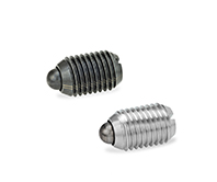 GN 615.1Spring plungersSteel / Stainless Steel, with bolt / with slotView Product
 -
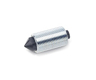
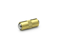 GN 614.2Spring plungerPress on type, ball double endedView Product
 -
 GN 250Indent blocksfor spring plungersView Product
 -
 GN 513Spring elementsView Product
 -
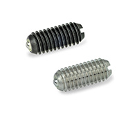 GN 615.8Spring plungersSteel, Stainless Steel, Ball with friction bearing, with slotView Product

