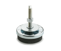
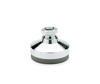
GN 148
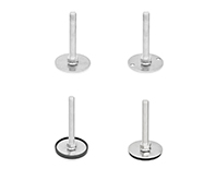
Leveling Feet
with Vibration Damping Element
Description
Specification
Types
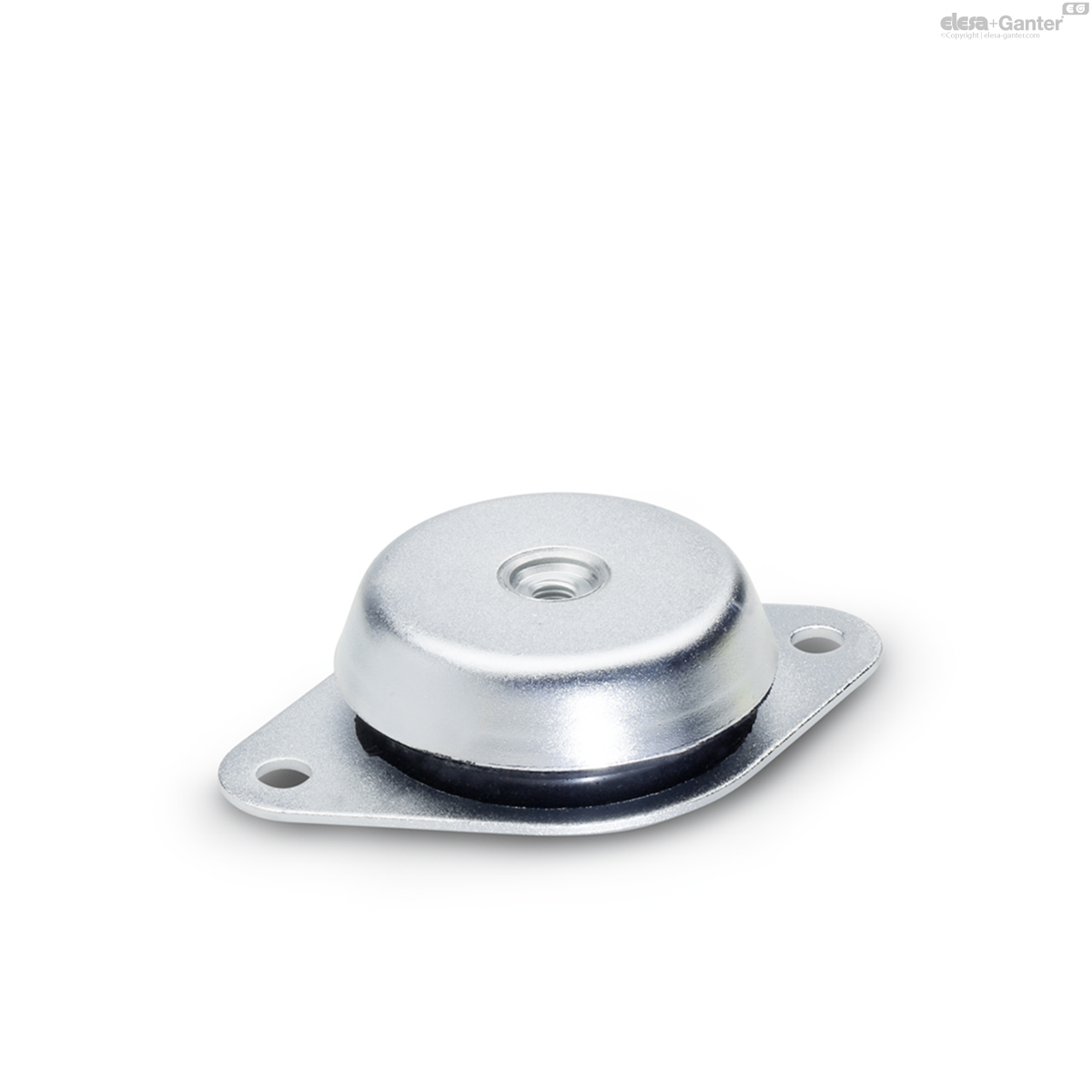
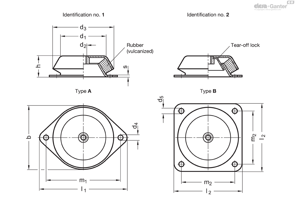
- Type A: with two-hole flange (d1 = 60 / 90 / 113)
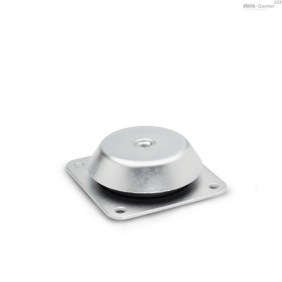
- Type B: with four-hole flange (d1 = 113 / 126)
Identification no.
- No. 1: without tear-off lock
- No. 2: with tear-off lock
Vibration damping element
Natural rubber (NR)
vulcanized
temperature resistant up to 80 °C
Hardness [Shore A ±5 °]
soft 43
medium 57
hard 68
Sheet metal
zinc plated, blue passivated
Threaded insert
Steel
zinc plated, blue passivated
Information
Levelling feet GN 148 are designed for setting up heavy machinery and units with insulation against vibrations.
This has a positive impact on the lifetime of machines and additionally reduces the noise pollution.
The structure is such that horizontal forces are also absorbed. The design with tear-off lock (Type 2) protects the levelling feet from destruction caused by tear-off under excessive tension loads.
The details relating to the load bearing capacity are non-binding recommended values and rule out any liability. They constitute no general warranty of quality and condition. The user must determine from case to case whether a product is suitable for the intended use.
Accessory
- Rubber pads GN 148.2
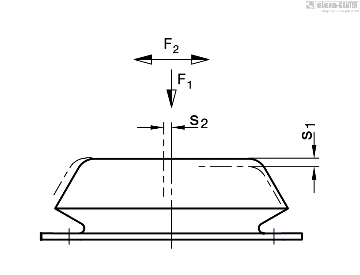
Technical information (Terms)
F1 = static load in vertical direction (pressure)
F2 = static load in horizontal direction (lateral thrust)
s1 = Compression in vertical direction (spring excursion) under load thorugh F1
s2 = Compression in vertical direction (spring excursion) under load through F2
Stiffness R:
is the load which causes the damping elements to be compressed by 1 mm (spring rate)
Equation for calculating the stiffness: R = F / S
The table below gives details on the maximum static load F, the maximum rated compression and the resulting stiffness R.
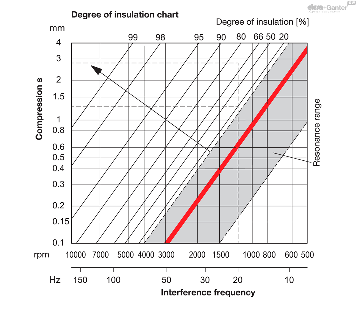
The method shown and the values given below allow the maximum degree of insulation of the vibration to be determined as a factor of the interfence frequency.
| d1 | Hardness in Shore | max. static load F1 in N | Stiffness R1 in N/mm | max. compression s1, in mm | max. static load F2 in N | Stiffness R2 in N/mm | Max. Compression s2 in mm |
| 60 | 43 | 1100 | 340 | 3.2 | 2300 | 770 | 3 |
| 60 | 57 | 1750 | 550 | 3.2 | 3400 | 1130 | 3 |
| 60 | 68 | 2800 | 930 | 3 | 4000 | 1330 | 3 |
| 90 | 43 | 1500 | 430 | 3.5 | 3000 | 750 | 4 |
| 90 | 57 | 2800 | 800 | 3.5 | 5000 | 1330 | 3.75 |
| 90 | 68 | 4500 | 1290 | 3.5 | 7000 | 1870 | 3.75 |
| 113 | 43 | 3500 | 1000 | 3.5 | 4500 | 1290 | 3.5 |
| 113 | 57 | 6500 | 1860 | 3.5 | 7500 | 2140 | 3.5 |
| 113 | 68 | 10000 | 2860 | 3.5 | 11000 | 3140 | 3.5 |
| 126 | 43 | 7500 | 2140 | 3.5 | 9000 | 2570 | 3.5 |
| 126 | 57 | 12500 | 3570 | 3.5 | 15000 | 4290 | 3.5 |
| 126 | 68 | 19000 | 5340 | 3.5 | 22500 | 6430 | 3.5 |
Terms
Interference frequency [Hz]:
is the frequency emanating from a machine, e.g. the
machine main shaft speed [rpm].
Static load F [N]:
is the load acting on each vibration-damping element (levelling foot).
Degree of insulation [%]:
is the measure for absorbing the interference frequency (damping).
Compression s [mm]:
is the change in height of the damping element (spring excursion).
Stiffness R [N/mm]:
is the load which causes a damping element to be
compressed by 1 mm (spring rate).
Determining the suitable levelling foot and the maximum degree of insulation
First, the static load F for each levelling foot must be determined. For well arranged levelling feet and the resulting even distribution of the load F, the static load is calculated using the following equation:
Weight force of the machine [N] / Number of levelling feet = Static load F [N] / per levelling foot
Once the static load F has been calculated, select a levelling foot from the table. Please note that the static load F should be as close as possible to the static load capacity, but without exceeding it. The associated stiffness R of the selected leg is also shown in the table.
The actual compression is then calculated using the equation below.
Static load F[N] / per levelling foot / Stiffness R [N/mm] = actual compression s [mm]
Starting from the actual compression s calculated, the maximum degree of insulation as factor of the interference frequency can now be read in the above chart.
To optimise the maximum degree of insulation, change the number of feet such that the static load F of each levelling foot is as close as possible below a static load capacity value given in the table. This will increase the compression s which, in turn, improves the degree of insulation.
In general, medium and high frequencies can be very well insulated with an adequate compression.
Example of application
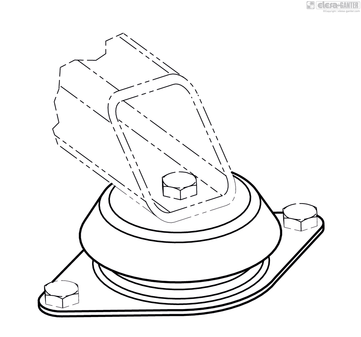
GN 148-A
| d1 | d2 | d3 | d4 | h | s | b | l1 | m1 | |||
|---|---|---|---|---|---|---|---|---|---|---|---|
| Code | Actions | ||||||||||
| GN 148-60-M10-A-1-43 | 60 | M 10 | 78 | 9 | 30 | 2 | 78 | 128 | 110 | 238 |
|
| GN 148-60-M10-A-1-57 | 60 | M 10 | 78 | 9 | 30 | 2 | 78 | 128 | 110 | 238 |
|
| GN 148-60-M10-A-1-68 | 60 | M 10 | 78 | 9 | 30 | 2 | 78 | 128 | 110 | 238 |
|
| GN 148-60-M10-A-2-43 | 60 | M 10 | 78 | 9 | 30 | 2 | 78 | 128 | 110 | 282 |
|
| GN 148-60-M10-A-2-57 | 60 | M 10 | 78 | 9 | 30 | 2 | 78 | 128 | 110 | 282 |
|
| GN 148-60-M10-A-2-68 | 60 | M 10 | 78 | 9 | 30 | 2 | 78 | 128 | 110 | 282 |
|
| GN 148-90-M12-A-1-43 | 90 | M 12 | 106 | 13 | 39 | 3 | 110 | 170 | 140 | 720 |
|
| GN 148-90-M12-A-1-57 | 90 | M 12 | 106 | 13 | 39 | 3 | 110 | 170 | 140 | 720 |
|
| GN 148-90-M12-A-1-68 | 90 | M 12 | 106 | 13 | 39 | 3 | 110 | 170 | 140 | 720 |
|
| GN 148-90-M12-A-2-43 | 90 | M 12 | 106 | 13 | 39 | 3 | 110 | 170 | 140 | 807 |
|
| GN 148-90-M12-A-2-57 | 90 | M 12 | 106 | 13 | 39 | 3 | 110 | 170 | 140 | 807 |
|
| GN 148-90-M12-A-2-68 | 90 | M 12 | 106 | 13 | 39 | 3 | 110 | 170 | 140 | 807 |
|
| GN 148-113-M16-A-1-43 | 113 | M 16 | 150 | 12.5 | 52 | 4 | 150 | 216 | 184 | 1715 |
|
| GN 148-113-M16-A-1-57 | 113 | M 16 | 150 | 12.5 | 52 | 4 | 150 | 216 | 184 | 1715 |
|
| GN 148-113-M16-A-1-68 | 113 | M 16 | 150 | 12.5 | 52 | 4 | 150 | 216 | 184 | 1715 |
|
| GN 148-113-M16-A-2-43 | 113 | M 16 | 150 | 12.5 | 52 | 4 | 150 | 216 | 184 | 1900 |
|
| GN 148-113-M16-A-2-57 | 113 | M 16 | 150 | 12.5 | 52 | 4 | 150 | 216 | 184 | 1900 |
|
| GN 148-113-M16-A-2-68 | 113 | M 16 | 150 | 12.5 | 52 | 4 | 150 | 216 | 184 | 1900 |
|

Enquiry Now
To allow us to respond to your enquiry promptly, please provide all required information.
Related Products
-
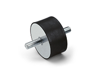
 DVA.4Rubber buffersRubber and steel or stainless steelView Product
 -
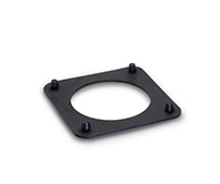 GN 148.2Rubber padsfor levelling feet GN 148View Product
 -
 GN 342.1Levelling feetwith vibration damping / female threadView Product
 -
DVA.1Rubber buffersRubber and steel or stainless steelView Product
-
LW.AVibration-damping levelling elementsSteel base and stemView Product
-
 GN 41Leveling FeetStainless SteelView Product
 -
DVA.6Rubber buffersRubber and steel or stainless steelView Product