

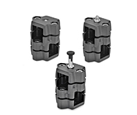
GN 147.7
Flanged Locking Slide Units
Aluminum
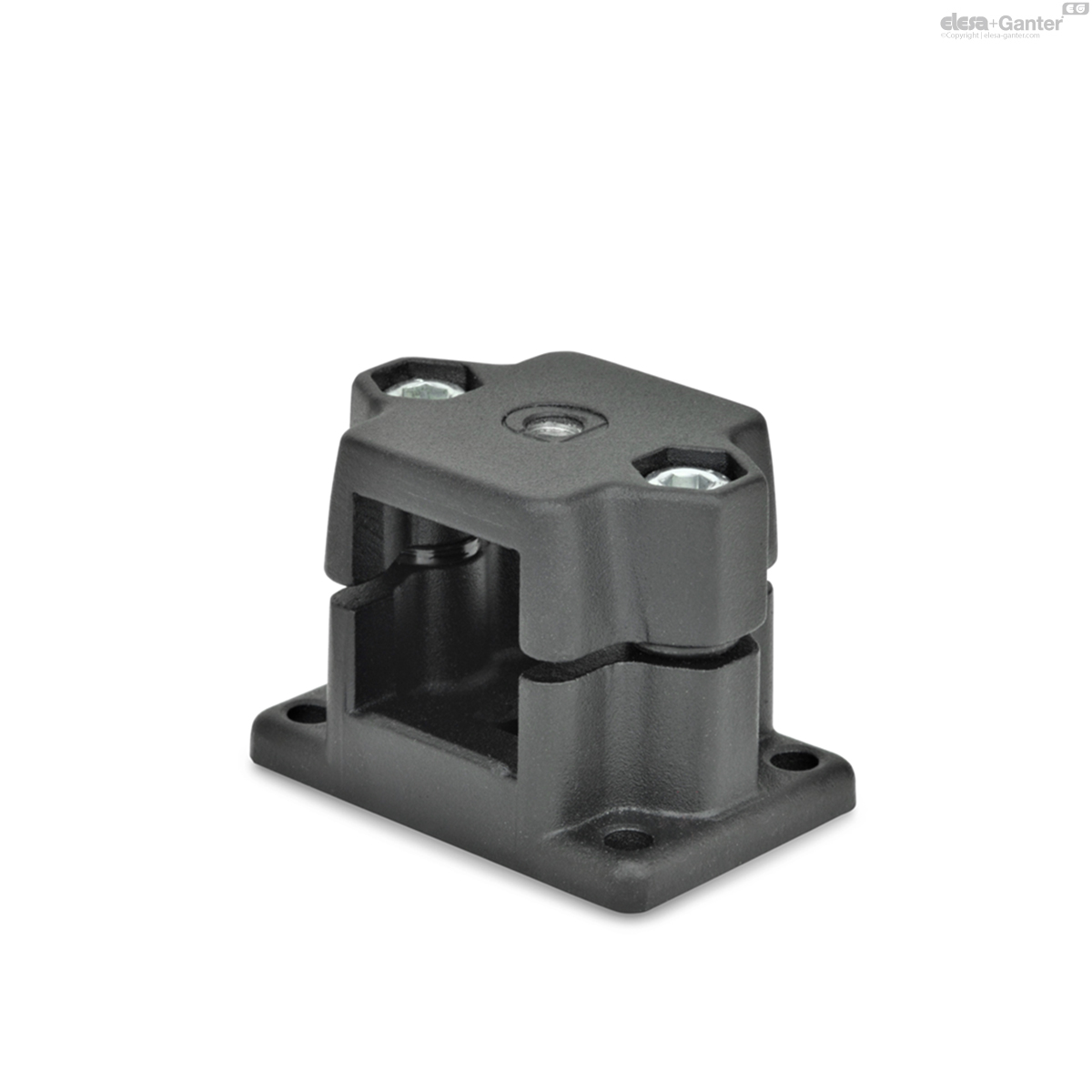
GN 147.7-G
Flanged Locking Slide Units
with thread
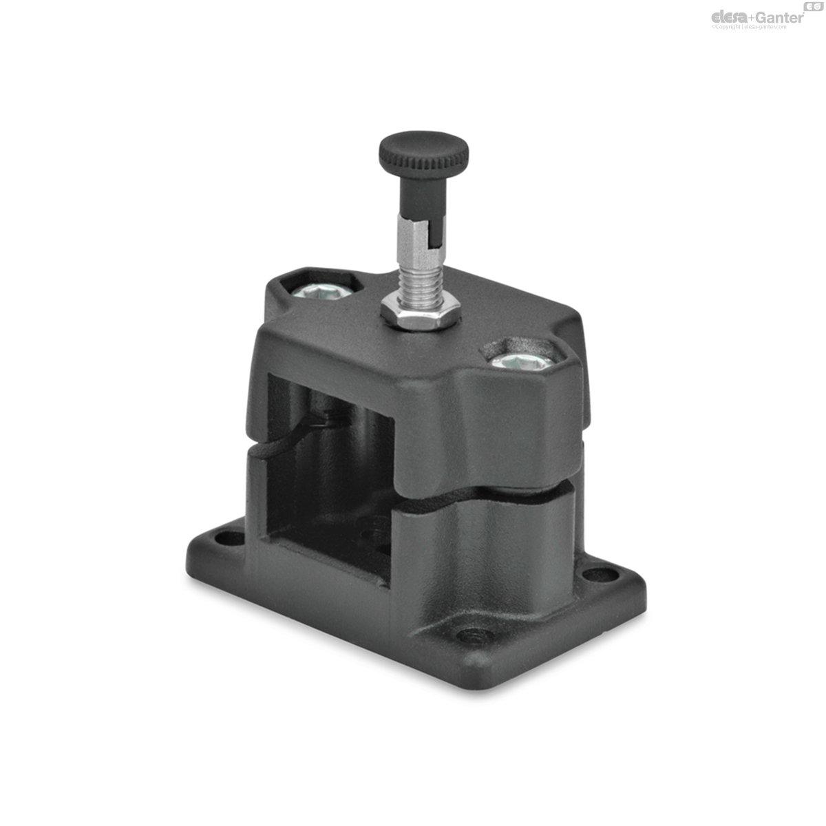
GN 147.7-R
Flanged Locking Slide Units
with indexing plunger
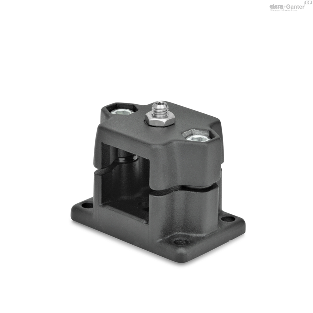
GN 147.7-D
Flanged Locking Slide Units
with spring plunger
Description
Specification
Type
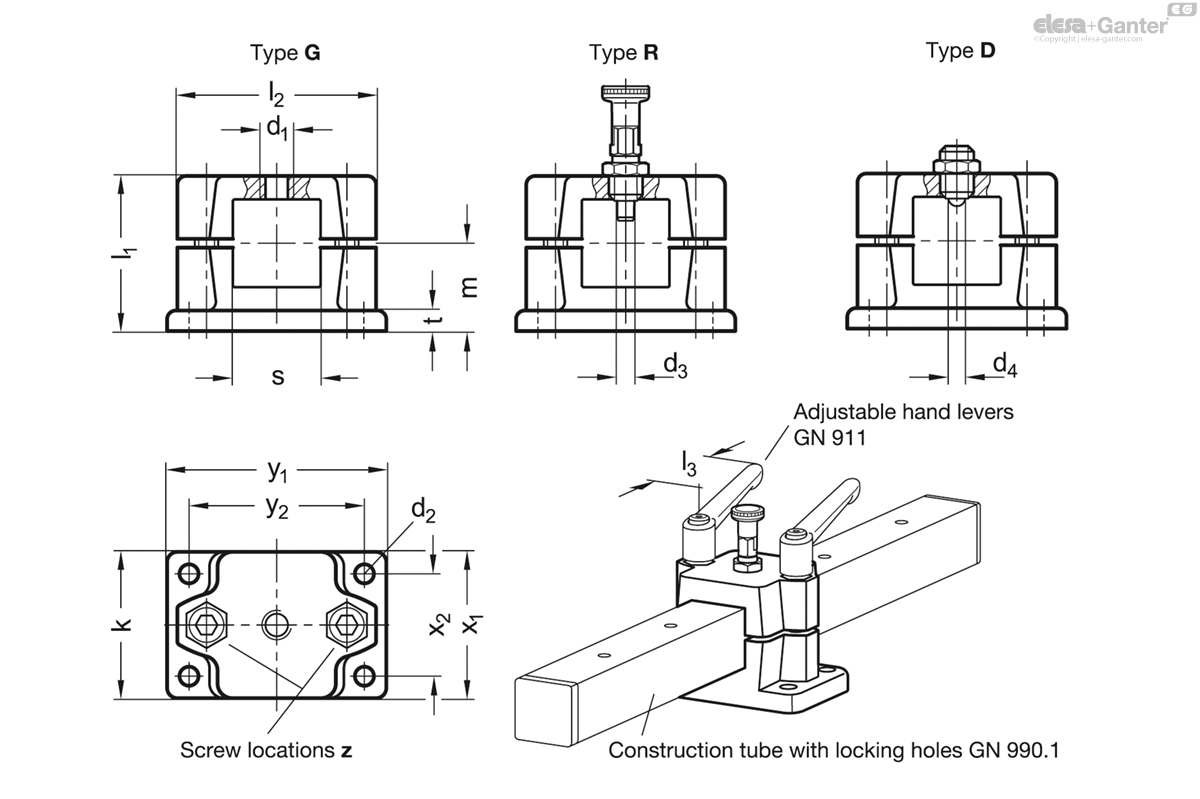
- Type G: With thread
- Type R: With indexing plunger
- Type D: With spring plunger
Aluminum
Powder coated
Black, RAL 9005, textured finish SW
Fastening elements / transfer elements
- Socket cap screws DIN 912
- Hex nuts DIN 985
- Centering bushings
Stainless steel AISI 304
Indexing plunger GN 717, type CK
- Plunger pin
Stainless steel AISI 303
- Knob
- Plastic (Polyamide PA)
- Black, matte finish
Spring plunger GN 615.9, type KN
- Stainless steel AISI 303
- Ball with friction bearing
- With internal hex
- Stainless steel lock nut ISO 4035
Information
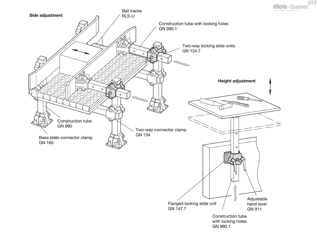
With flanged locking slide units GN 147.7, recurring positions along a square construction tube can be moved to easily and quickly. The required holes for type R or countersinks for type D can be created by the user according to the design instructions or ordered as completely finished construction tubes with locking holes GN 990.1 .
For quick clamping without tools, the socket cap screws at the screw locations z, can be replaced by the adjustable hand levers GN 911 listed in the table as accessories.
Centering bushings in the pass-through holes eliminate the axial play between the top and bottom parts of the locking slide units.
Flanged locking slide units GN 147.7 are delivered with unmounted indexing plunger (Type R) or spring plunger (Type D). Type G with thread is universally suitable for specific applications.
Accessory
- Adjustable Hand Levers GN 911
Technical information
- Stainless Steel Characteristics
Construction information
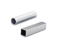
The square dimensions of the locking slide units are designed for construction tubes GN 990. These can be fitted with locking holes (B or S) by the user according to the dimensions specified in the table.
Construction tubes with locking holes can be ordered as standard part GN 990.1 cut to length and completely ready for installation.
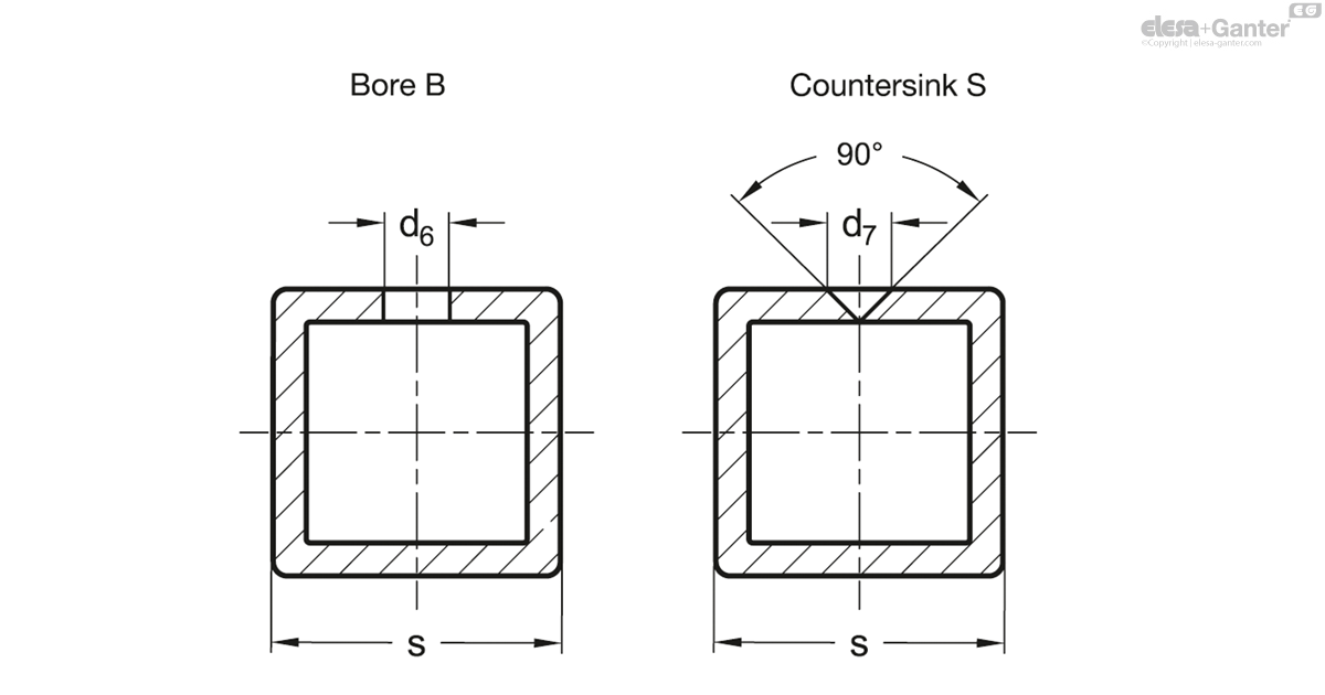
| S Square | d6 + 0.3 Bore B (for type R) | d7 +0.3 Countersink (for type D) | For locking slides |
| V 25 | B 5 | S 2.5 | V 25 |
| V 30 | B 5 | S 2.5 | V 30 |
| V 40 | B 8 | S 4.5 | V 40 |
| V 50 | B 8 | S 4.5 | V 50 |
Application examples
GN 147.7-G
| d1 | s Square | d2 | d3 Pin -0.05 Bore +0.03/+0.08 |
k Clamping length | l1 | l2 | m | t | x1 | x2 | y1 | y2 | z Screw locations |
Accessory Recom. hand lever GN 911 for z l3 |
|||
|---|---|---|---|---|---|---|---|---|---|---|---|---|---|---|---|---|---|
| Code | Actions | ||||||||||||||||
| GN 147.7-V25-G-SW | M 8 | V 25 | 6.5 | 5 | 50 | 53 | 68 | 30 | 7 | 50 | 35 | 75 | 60 | M8-35 | 78 | 248 |
|
| GN 147.7-V30-G-SW | M 8 | V 30 | 6.5 | 5 | 50 | 53 | 68 | 30 | 7 | 50 | 35 | 75 | 60 | M8-35 | 78 | 233 |
|
| GN 147.7-V40-G-SW | M 12 | V 40 | 11 | 8 | 76 | 81.5 | 98 | 46.5 | 14 | 76 | 50 | 115 | 90 | M10-60 | 92 | 711 |
|
| GN 147.7-V50-G-SW | M 12 | V 50 | 11 | 8 | 76 | 81.5 | 98 | 46.5 | 14 | 76 | 50 | 115 | 90 | M10-60 | 92 | 660 |
|

Enquiry Now
To allow us to respond to your enquiry promptly, please provide all required information.
Related Products
-
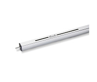
 GN 990Construction TubesAluminum / Stainless Steel, for Tube Clamp ConnectorsView Product
 -
 GN 134.7Two-Way Locking Slide UnitsAluminumView Product
 -
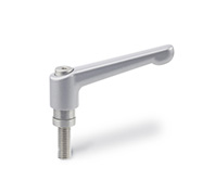 GN 911Adjustable Hand Leversfor Tube Clamp Connectors / Linear Actuator ConnectorsView Product
 -
 GN 291.1Square Linear Actuatorswith Right or Left Hand ThreadView Product

