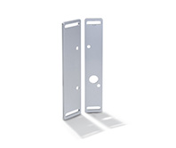
GN 139.1
Hinges with Safety Switch
Zinc Die Casting
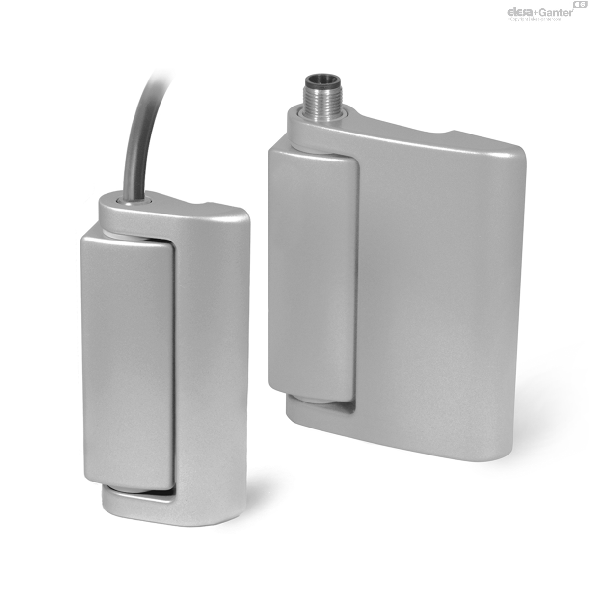
Description
Specification
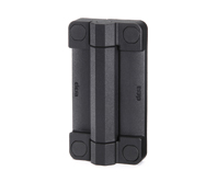
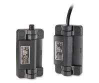
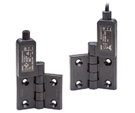
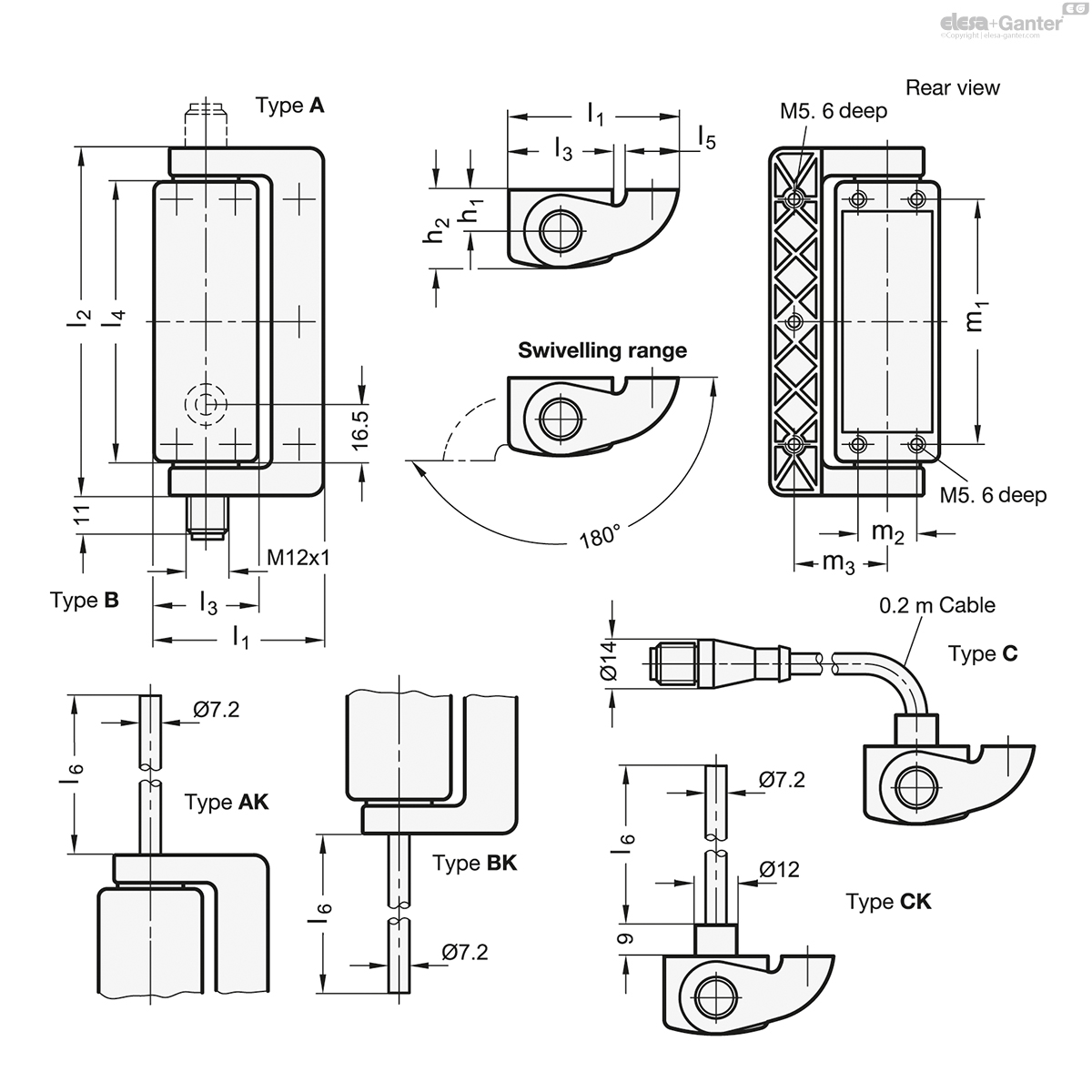
Types
- Type A: Connector plug at the top
- Type AK: Cable at the top
- Type B: Connector plug from the bottom
- Type BK: Cable from the bottom
- Type C: Connector plug on the backside, with 0.2 m cable
- Type CK: Cable from the back
Zinc die casting
plastic coated
silver metallic
Pin
Stainless Steel AISI 303
Information
Hinges GN 139.1 with integrated safety switches have been designed for monitoring doors and covers of machines and plants. Opening the door will activate the switch contacts which, in turn, will then e.g. interrupt a protective circuit via break contact (NC) and at the same time signal the door opening by closing a normally open contact element (NO).
The contact blocks are fitted with positive opening slow-action contacts, i.e. they will definitely be separated when activated and have no hysteresis. The angle at which the switching points are reached are adjustable (see contact travel diagram).
Together with the integrated contact blocks, the hinges are a compact, easy to mount unit with an attractive design. The mounting from the back make the hinge more tamper-proof.
- Operating instruction GN 139.1
Technical Information
- Load rating information of hinges
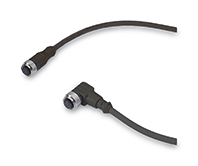
Accessories
Cable with connection coupling
8-pole, 5 or 10 meters long:
- Cables with conntector coupling GN 330 -M12x1-8-G-5.
- Cables with conntector coupling GN 330 -M12x1-8-G-10.
- Mounting plates, flat GN 139.3
- Mounting plates, angled GN 139.4
On request
- Hinges with operation angle > 0°
- Hinges with other contact terminations
Mechanical features
| Mechanical features | ||||
| Maximum load Information with safety factor Examples of calculation | Load direction | |||
| - | l1 = 49 | 1500 N | 1000 N | 1000 N |
| - | l1 = 79 | 750 N | 500 N | 500 N |
| Fixing | from the back, 7 x threads M5, 6 mm deep | |||
| Recommended torque | 5 Nm (Screws M5) | |||
| Protection class | IP67 / IP69K (Mind the cable conduit!) | acc. to EN 60529 | ||
| Switching principle, contact opening | Slow-action contacts, force-fitted, with positive opening | acc. to IEC 60947-5-1, K | ||
| Contact material | Silver alloy | |||
| Operating travel diagram (scheme) | The switching points are adjustable up to 4° in direction of 0°. | |||
| Maximum operating frequency | 600 operating cycles / hour | acc. to IEC 60947-5-1, one operating cycle includes one opening / one closing action | ||
| Mechanical life span | 106 operating cycles | acc. to IEC 60947-5-1, one operating cycle includes one opening / one closing action | ||
| Actuating speed | min. 2° / second, max. 90° / second | acc. to IEC 60947-5-1, one operating cycle includes one opening / one closing action | ||
Electrical features / Safety features
| Electrical features / Safety features | ||||
| Utilization category | AC 15: 24 Vac / 2A / DC 13: 24 Vdc / 2A (connector plug), AC 15: 250 Vac / 4A / DC 13: 250 Vdc / 0,3 A (cable) | acc. to EN 60947-5-1 | ||
| Contacts, termination | ||||
| 8-pole connector M12 | ||||
| or cable with 2 m or 5 m length | ||||
| Pin and cable assignment | ||||
| Type of cable | Type N 7 x0.5 mm2, jacket PVC H05VV-F | acc. to IEC 60332-1-2 et seqq. | ||
| Short-circuit current | 1000 A | acc. to EN 60947-5-1 | ||
| Rated insulation voltage | 30 V AC / 36 V DC (connector plug) / 250 Vac (cable) | |||
| Short-circuit protection | 2 A, 500 V, Typ gG (connector plug) / 6 A, 500 V, Typ gG (cable) | |||
| Ambient temperature | - 25 °C up to + 80 °C | |||
| Degree of pollution, external | 3 | acc. to EN 60947-5-1 | ||
| Mission time (TM) | 20 years | acc. to EN ISO 13849-1 | ||
| Number of cycles (B10 d) | 5 000 000 | acc. to EN 61820-2 | ||
Approvals, Conformities, Applicability
| Approvals, Conformities, Applicability | ||||
| Low-voltage switchgear and controlgear | EN 60947-1/2007 | |||
| CE declaration | EN 60947-1-5 : 2004 + | |||
| IMQ: CA02.03746 | A1/2009 | |||
| UL: E 131787 | ||||
| Safety applications | up to SIL 3 / PL e | acc. to EN ISO 13849-1 | ||
Other important details and hints are given in the operating instruction for GN 139.1 which is included with every delivery and which is also available as PDF download from „www.elesa-ganter.com“ under ‚Downloads‘.
The hinges with safety switch must be mounted and commissioned by qualified technical personnel in compliance with the details given in the operating instruction and with the national and international rules and regulations and the applicable standards. Elesa+Ganter will assume no statutory liability for missing or incorrect information and for any consequences arising therefrom.
GN 139.1
| l1 | l2 | l3 | l4 | l5 | l6 in m | h1 | h2 | m1 | m2 | m3 | |||
|---|---|---|---|---|---|---|---|---|---|---|---|---|---|
| Code | Actions | ||||||||||||
| GN 139.1-49-101-A | 49 | 101 | 30 | 81 | 15 | - | 12 | 22.5 | 71 | 17 | 27 | 325 |
|
| GN 139.1-49-101-AK-2 | 49 | 101 | 30 | 81 | 15 | 2 | 12 | 22.5 | 71 | 17 | 27 | 511 |
|
| GN 139.1-49-101-AK-5 | 49 | 101 | 30 | 81 | 15 | 5 | 12 | 22.5 | 71 | 17 | 27 | 730 |
|
| GN 139.1-49-101-B | 49 | 101 | 30 | 81 | 15 | - | 12 | 22.5 | 71 | 17 | 27 | 325 |
|
| GN 139.1-49-101-BK-2 | 49 | 101 | 30 | 81 | 15 | 2 | 12 | 22.5 | 71 | 17 | 27 | 511 |
|
| GN 139.1-49-101-BK-5 | 49 | 101 | 30 | 81 | 15 | 5 | 12 | 22.5 | 71 | 17 | 27 | 730 |
|
| GN 139.1-49-101-C | 49 | 101 | 30 | 81 | 15 | - | 12 | 22.5 | 71 | 17 | 27 | 364 |
|
| GN 139.1-49-101-CK-2 | 49 | 101 | 30 | 81 | 15 | 2 | 12 | 22.5 | 71 | 17 | 27 | 519 |
|
| GN 139.1-49-101-CK-5 | 49 | 101 | 30 | 81 | 15 | 5 | 12 | 22.5 | 71 | 17 | 27 | 742 |
|
| GN 139.1-79-101-A | 79 | 101 | 30 | 81 | 30 | - | 12 | 22.5 | 71 | 17 | 50 | 425 |
|
| GN 139.1-79-101-AK-2 | 79 | 101 | 30 | 81 | 30 | 2 | 12 | 22.5 | 71 | 17 | 50 | 613 |
|
| GN 139.1-79-101-AK-5 | 79 | 101 | 30 | 81 | 30 | 5 | 12 | 22.5 | 71 | 17 | 50 | 830 |
|
| GN 139.1-79-101-B | 79 | 101 | 30 | 81 | 30 | - | 12 | 22.5 | 71 | 17 | 50 | 425 |
|
| GN 139.1-79-101-BK-2 | 79 | 101 | 30 | 81 | 30 | 2 | 12 | 22.5 | 71 | 17 | 50 | 613 |
|
| GN 139.1-79-101-BK-5 | 79 | 101 | 30 | 81 | 30 | 5 | 12 | 22.5 | 71 | 17 | 50 | 830 |
|
| GN 139.1-79-101-C | 79 | 101 | 30 | 81 | 30 | - | 12 | 22.5 | 71 | 17 | 50 | 457 |
|
| GN 139.1-79-101-CK-2 | 79 | 101 | 30 | 81 | 30 | 2 | 12 | 22.5 | 71 | 17 | 50 | 619 |
|
| GN 139.1-79-101-CK-5 | 79 | 101 | 30 | 81 | 30 | 5 | 12 | 22.5 | 71 | 17 | 50 | 843 |
|

Enquiry Now
To allow us to respond to your enquiry promptly, please provide all required information.
Related Products
-
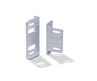 GN 139.4Mounting platesfor hinges with safety switch GN 139.1 / GN 139.2, angledView Product
 -
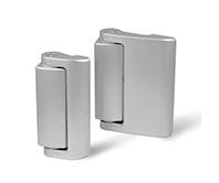 GN 139.2Hinges without safety switchZinc die castingView Product
 -
 PMW.CFSW. and CFMW. assembly kit for profilesSUPER-technopolymerView Product
 -
CFMW.HingesSUPER-technopolymerView Product
-
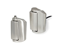 GN 139.5Hinges with safety switchStainless SteelView Product
 -
 GN 139.3Mounting platesfor hinges with safety switch GN 139.1 / GN 139.2, flatView Product
 -
 GN 330Cables with Connector CouplingView Product
 -
CFSW.Hinges with built-in safety switchSUPER-technopolymerView Product
-
CFSQHinges with built-in safety switchSUPER-technopolymerView Product