

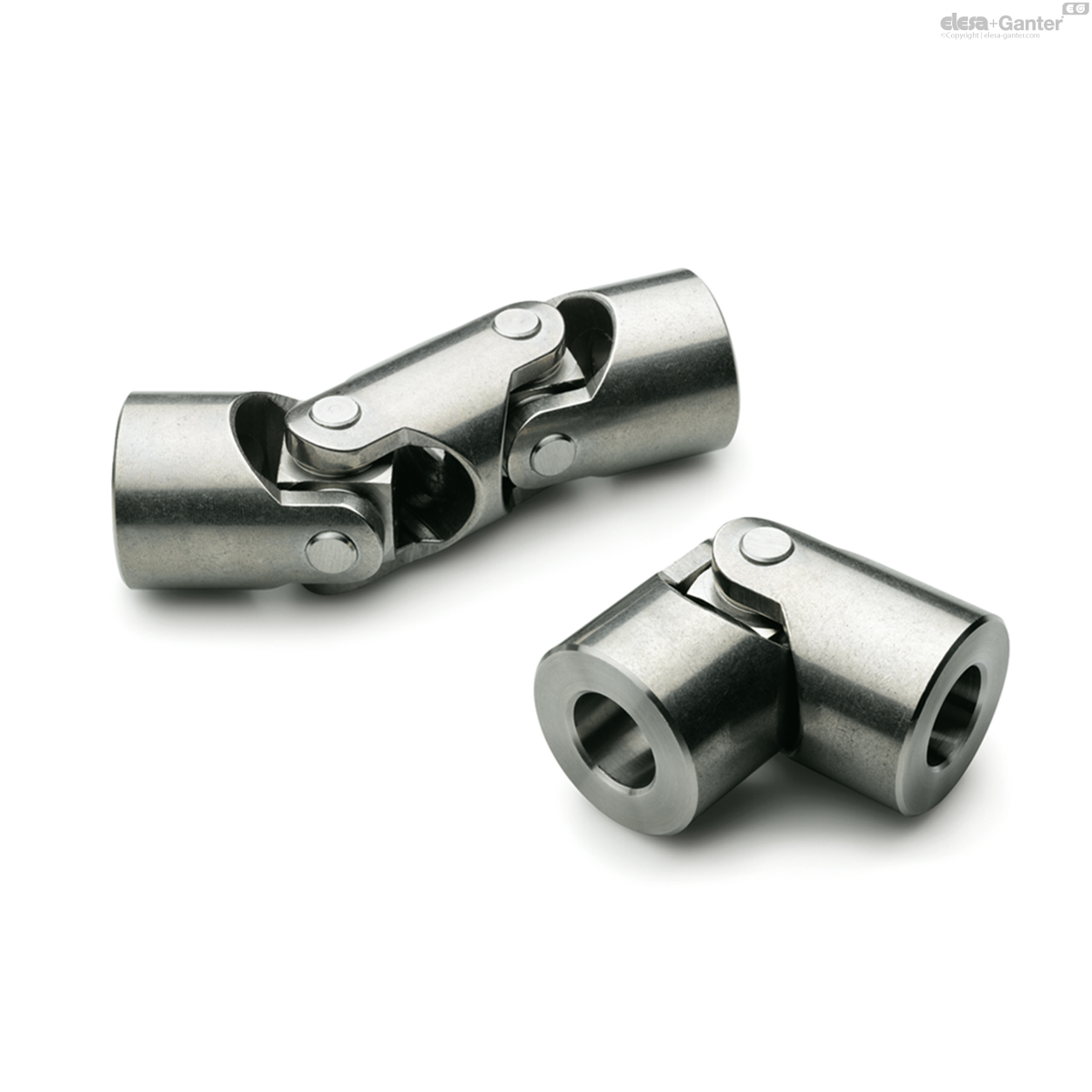
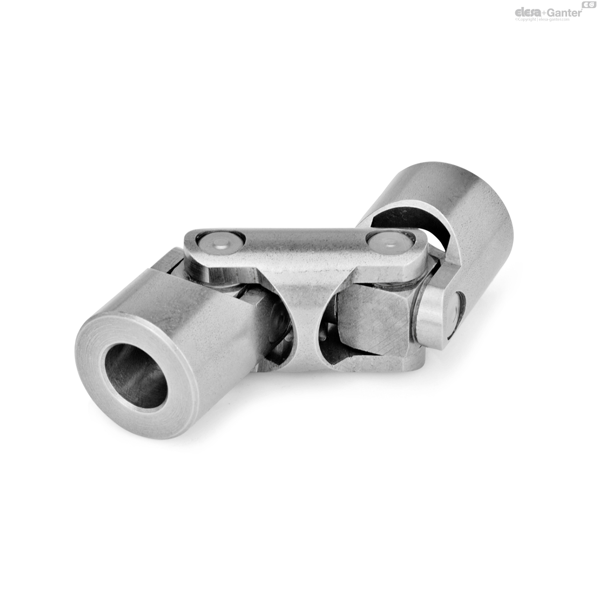
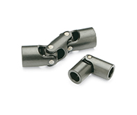
DIN 808
Universal Joints with Friction Bearing / Needle Bearing
Steel / Stainless Steel, Single or Double
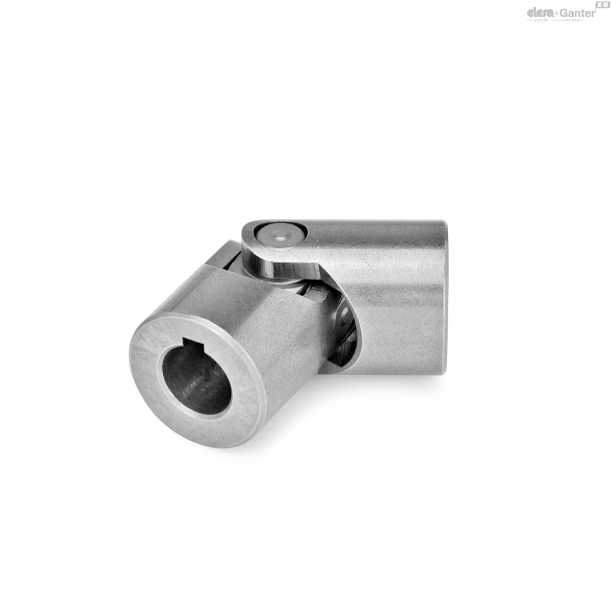
DIN 808-ST
Universal Joints with Friction Bearing / Needle Bearing
Steel, friction bearing
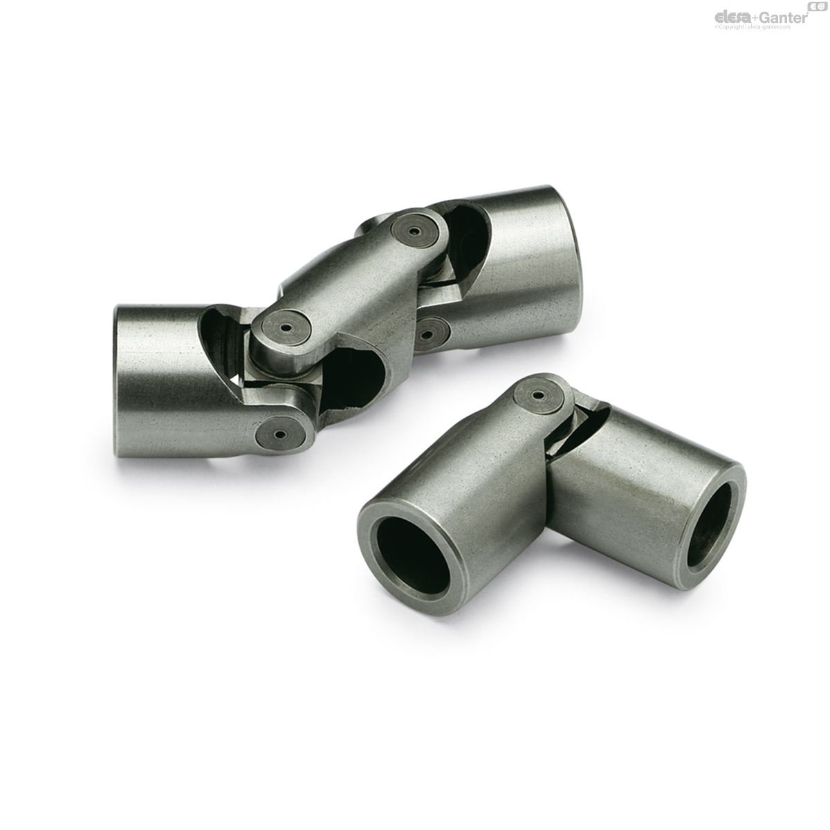
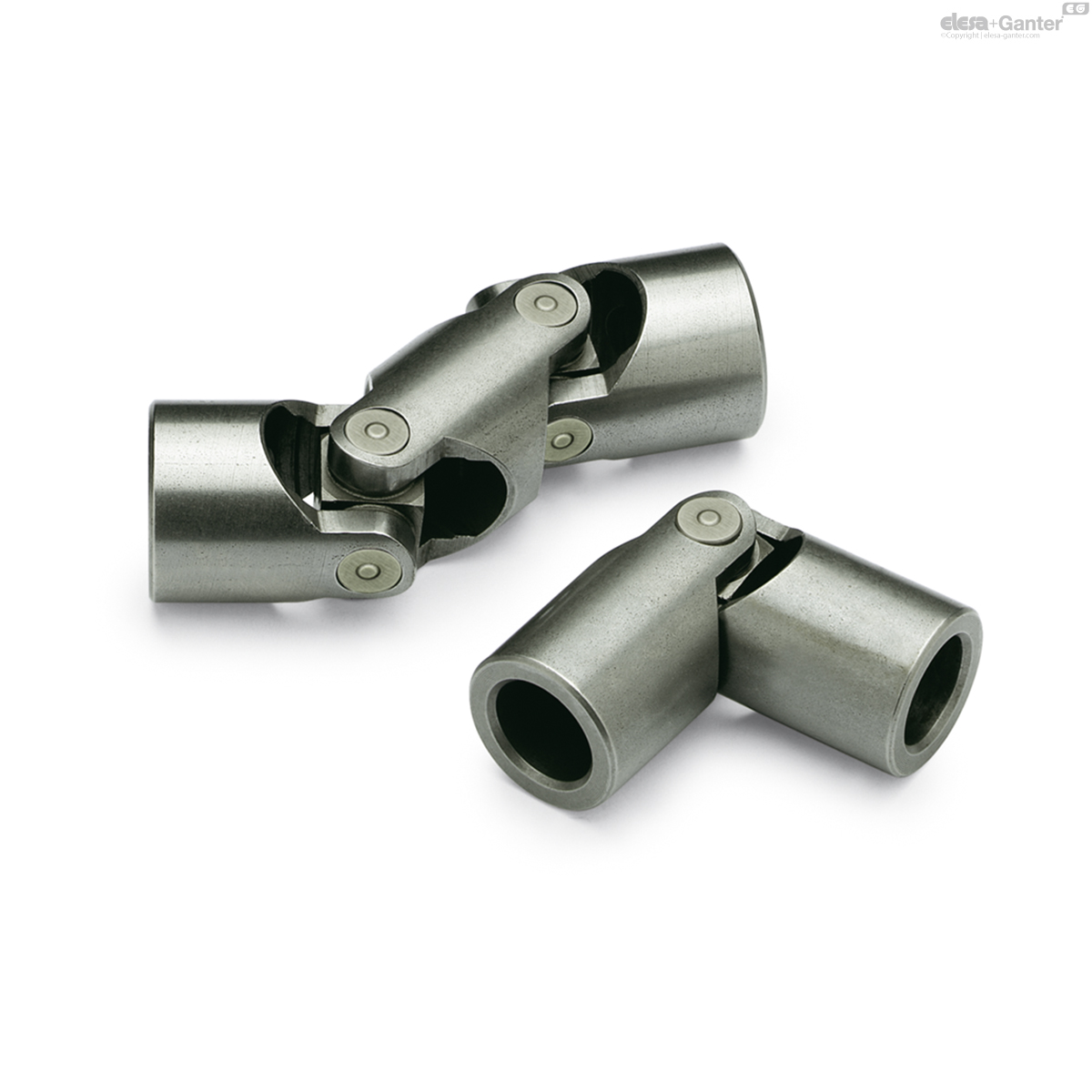
DIN-808-ST
Universal Joints with Friction Bearing / Needle Bearing
Steel, needle bearing
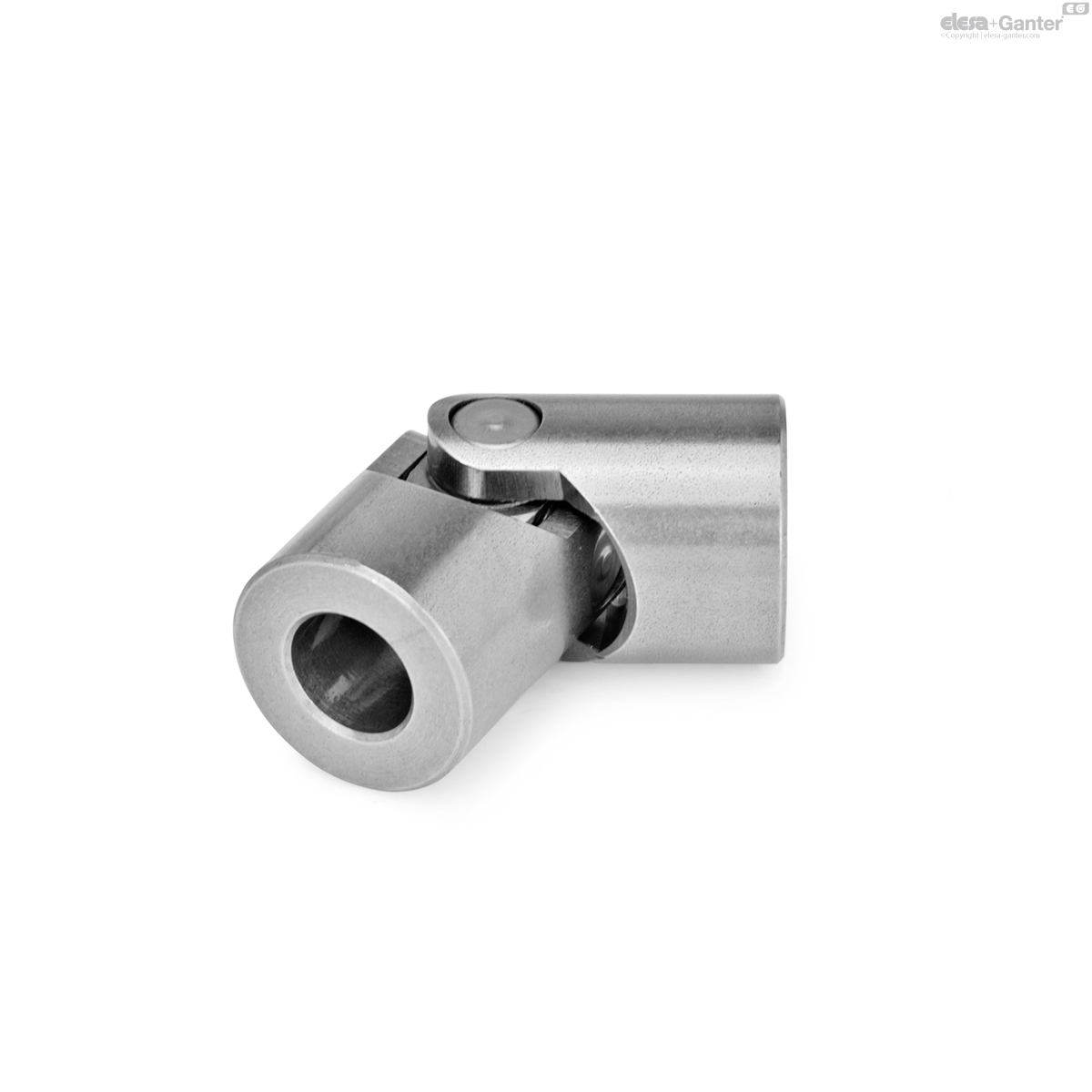
DIN 808-NI
Universal Joints with Friction Bearing / Needle Bearing
Stainless Steel, friction bearing

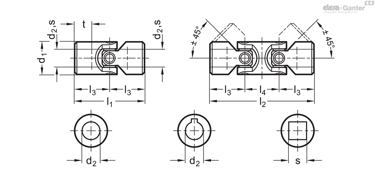
Description
Specification
Universal Joints with Friction Bearing
Version in steel
Bore codes
- Version B: Without keyway
- Version K: With keyway
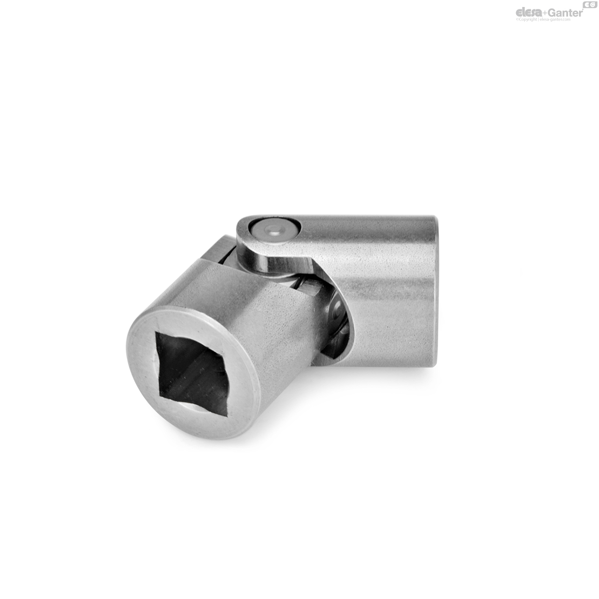
- Version V: With square
Types
- Type EG: Single, friction bearing
- Type DG: Double, friction bearing
Steel
Plain
Joint bearing areas / pins / bearing sleeves
Case-hardened
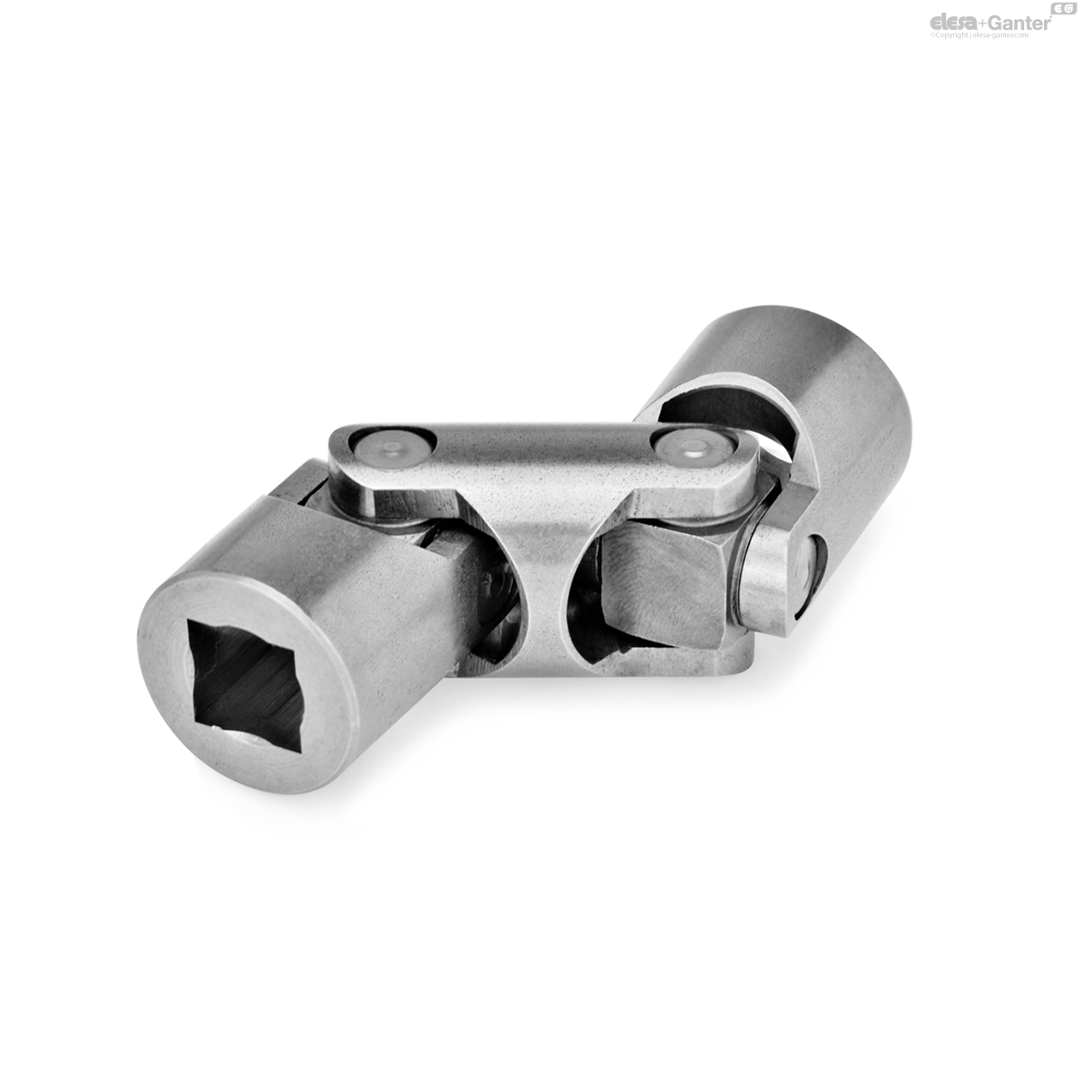
Universal Joints with Needle Bearing
Version in steel
Bore codes
- Version B: Without keyway
- Version K: With keyway
- Version V: With square
Types
- Type EW: Single, needle bearing
- Type DW: Double, needle bearing
Steel
Plain
Joint bearing areas, pins
Case-hardened
Universal Joints with Friction Bearing
Version in stainless steel
Bore codes
- Version B: Without keyway
- Version K: With keyway
- Version V: With square
Types
- Type EG: Single, friction bearing
- Type DG: Double, friction bearing
Stainless steel AISI 304 NI
Information
The permissible r.p.m. of universal joints with friction bearing DIN 808 is to a large extent dependent on the type of application such as load, duration, angular disposition as well as lubrication . For over 1000 r.p.m. universal joints with needle bearing should be used. For continuous use ample lubrication is essential. This achieved by fitting the joint with a grease filled gaiter GN 808.1.
The permissible r.p.m. of universal joints with needle bearings DIN 808 is higher than for those with friction bearings, but is still dependent on the load, duration of use as well as angular disposition. Ideal applications allow speeds of up to 4000 r.p.m . Needle bearings give the universal joints at 3° to 5° angular disposition a considerably higher degree of efficiency than those fitted with friction bearings. The needle bearings have a permanent lubrication and thus do not require servicing. Information regarding the selection of universal joints with needle bearing.
Since the moveable parts are not surface treated, i.e. not case-hardened, the possibilities of application of these universal joints are much more limited compared to the ones made of standard steel. Therefore, the guide lines for the selection of universal joints with friction bearing according to the diagram may be applied at a limited extent only. Rotational speeds over 200 min may become critical. For continuous use of the stainless steel universal joints, ample lubrication is very important. This achieved by fitting the joint with a grease filled gaiter GN 808.1. The order example refers to universal joints with equal bores both ends d2 or s.
On request
- With other or unequal bores
Technical information
- Keyway DIN 6885
- Cross holes GN 110.1
- ISO-Fundamental Tolerances
- Stainless Steel Characteristics
Mounting information
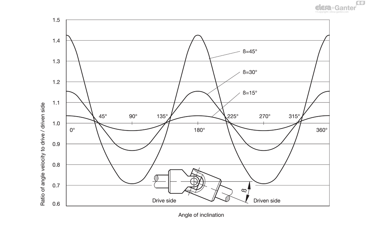
The single universal joints transfer the initial smooth rotation as an irregular rotation. One revolution of the drive shaft via single universal joint will cause the driven shaft to accelerate and decelerate twice. The extent of the irregularity depends on the operating angle ß.
In order to obtain a smooth rotation of the driven shaft two single or one double universal joint is required. In such cases where minor irregularities in the movement are acceptable or where minor operating angles are the norm a single universal joint will do.
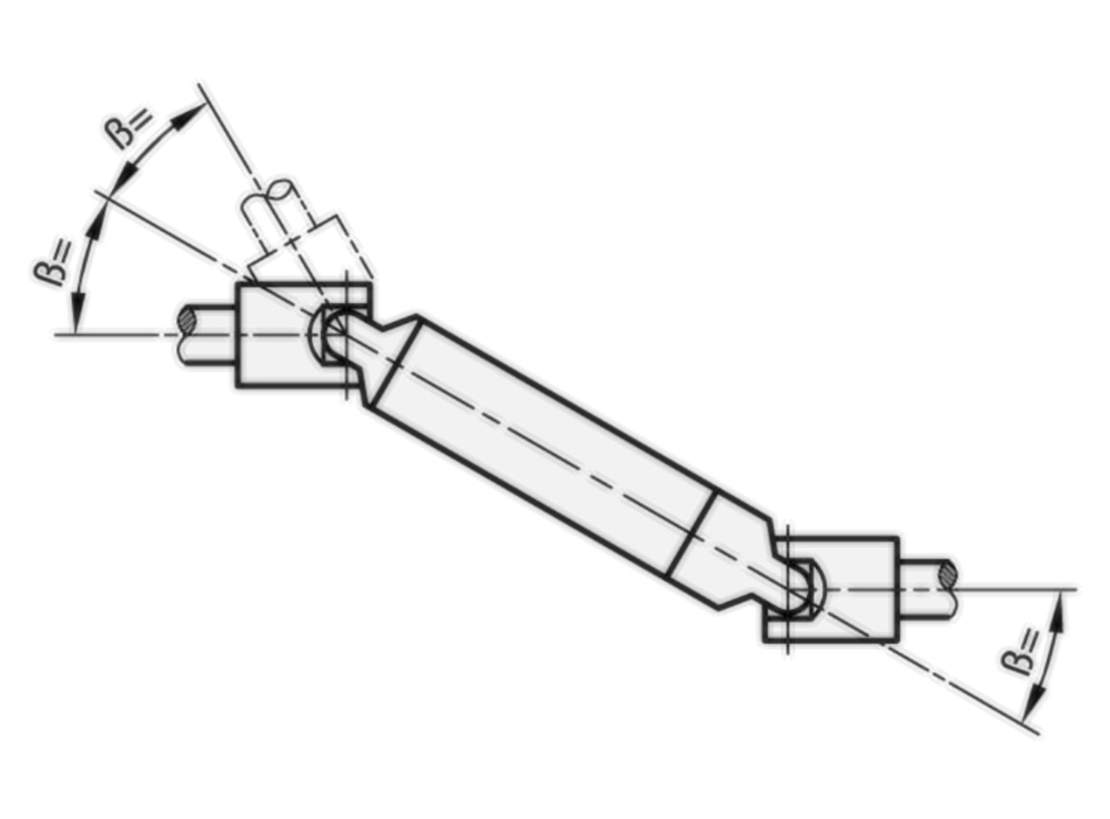
For a smooth transfer of a rotating speed, the angle of inclination ß must be equal at both ends of the connecting shaft.
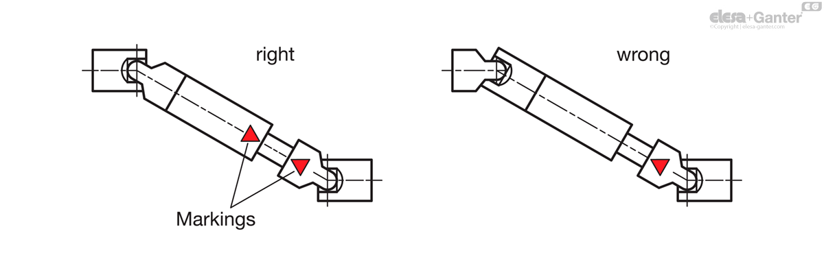
Due to a misconnection of the universal joint shafts, the irregular rotation of each joint is not compensated, but strengthened. This allows joint bearings and wedge profiles to be destroyed. For this reason, the markings of the universal joint shaft halves have to be opposite to each other.
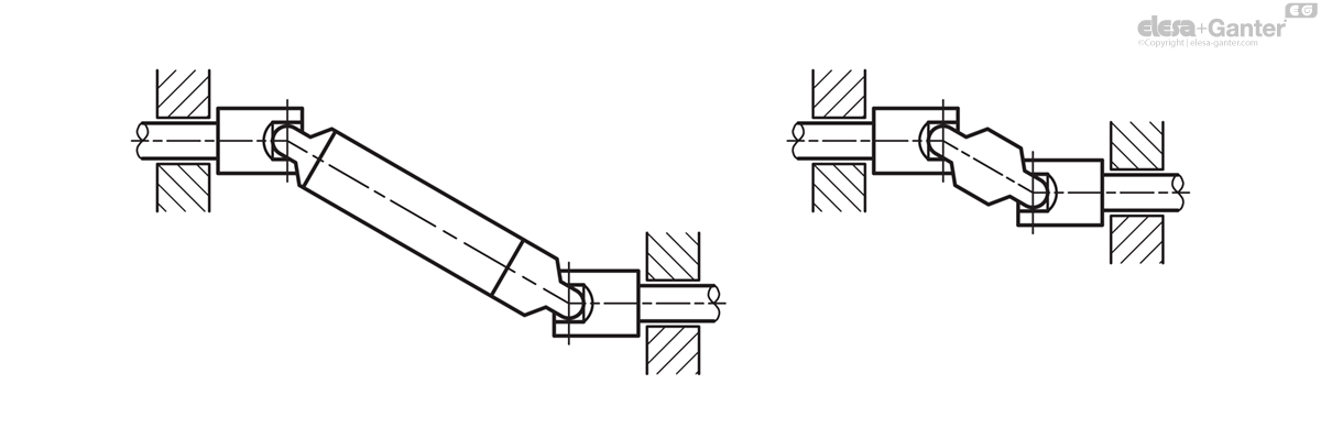
Furthermore the bearings must be as close as possible to the universal joints.
For continuous operation of universal joints with friction bearings adequate lubrication is essential. If drip lubrication is not possible they should be lubricated at least once a day. It is also possible to fit the universal joint with a gaiter GN 808.1 which can be filled with oil or grease.
Determining the Size
Universal joints with friction bearing, Type EG
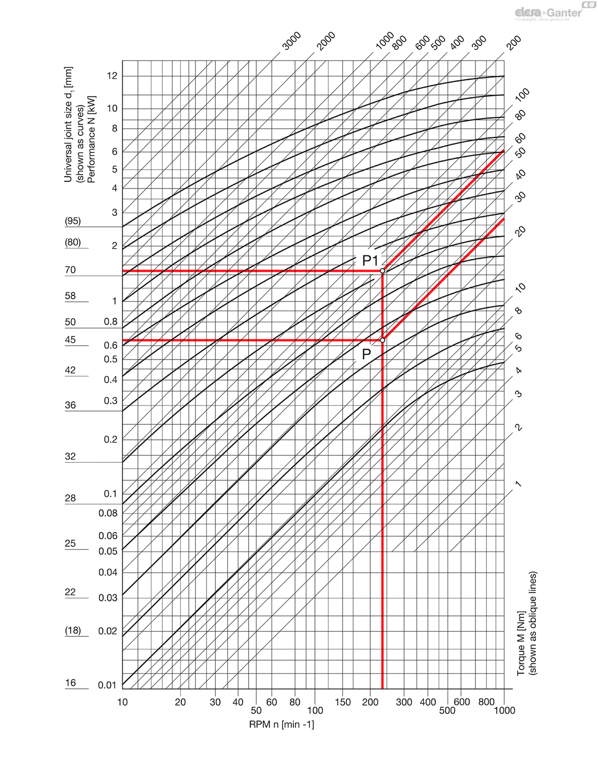
The table shows the transferable output N and/or torques M of universal joints DIN 808, type EG (single friction bearing) in relation to the RPM n.
The values are only applicable to a constant speed of rotation, constant load and an operating inclination angle of max. 10°. They are not applicable to universal joints in Stainless Steel.
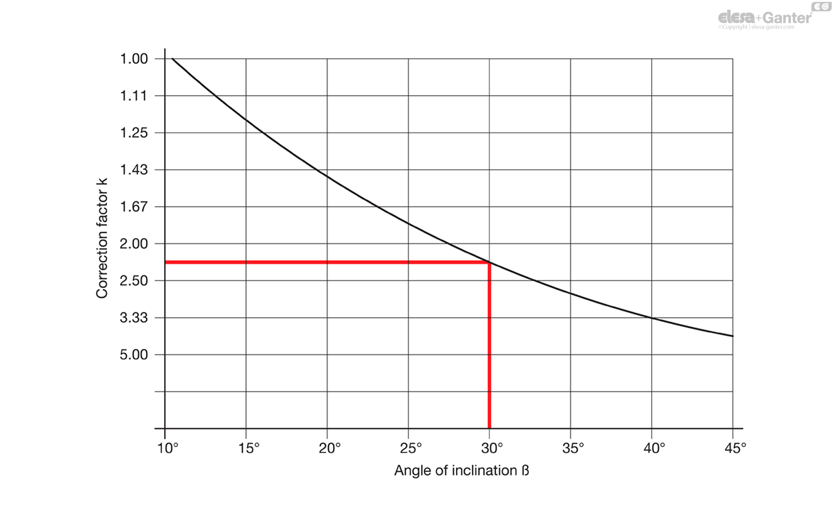
For larger inclination angles ß a nominal output N increased by the correction coefficient k and/or a nominal torque M has to be selected (see example below).
Conversion formular:
Torque M [Nm] = 9550 N[kW]/n [min-1]
Output N [kW] = M [Nm] x n [min-1]
1 kW = 1.36 PS / 1 PS = 0.736 kW
Example 1
Output to be transferred N = 0.65 kW
R.p.m. n = 230 min-1
Angle of inclination ß = 10°
Correction coefficient k = 1
Indicative output N‘= Nominal output N
Intersection point P results from 0.65 kW and 230 min-1 (which corresponds to a torque of 27 Nm).
The next size up universal joint corresponding to point P is the model with a diameter d1 = 25.
Example 2
Torque to be transferred M = 27 Nm
R.p.m. n = 230 min-1
Angle of inclination ß = 30°
Correction coefficient k = 2.25
Indicative torque = 2.25 x 27 Nm = 60 Nm
Intersection point P1 results from 61 Nm and 230 min-1 (which is equivalent to an indicative output N = 1.47 kW).
The next size up universal joint corresponding to P1 is the model with a diameter d1 = 36.
Universal joints with friction bearing, Type EW
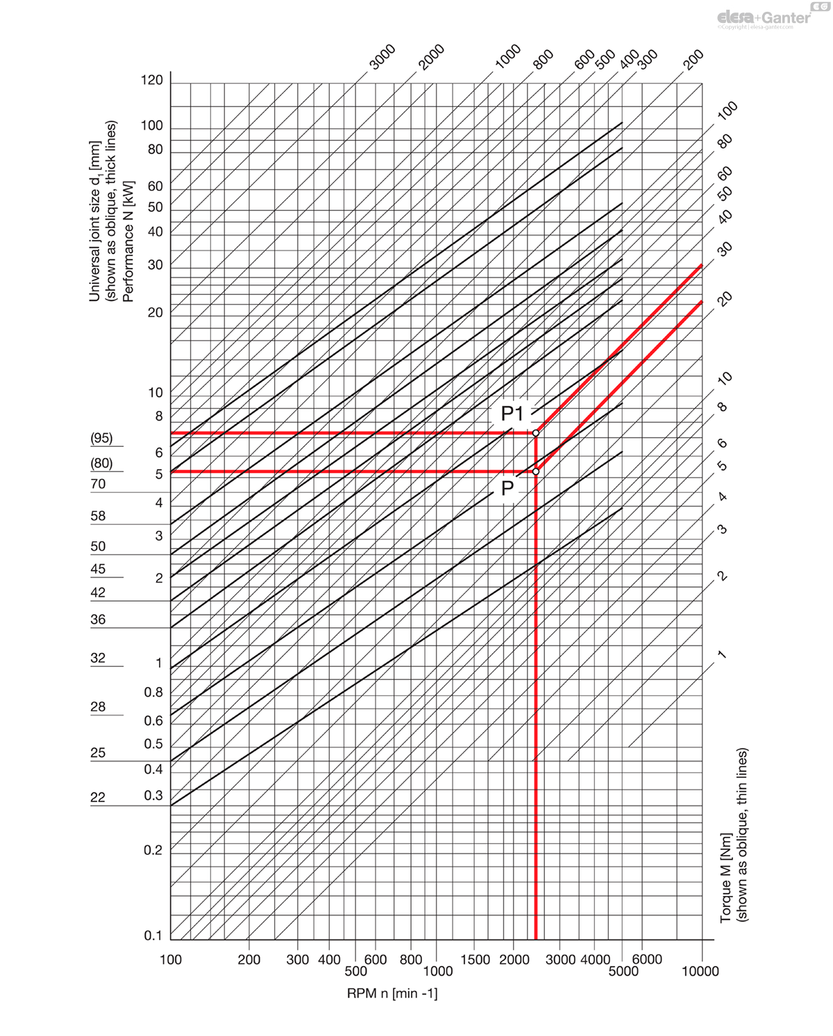
The table shows the transferable output N and/or torques M of universal joints DIN 808, type EW (single jointed, needle bearing) in relation to the RPM n.
The values are only applicable to a constant speed of rotation, constant load and an operating inclination angle of max. 10°.
For larger inclination angles ß a nominal output N increased by the correction coefficient k and/or a nominal torque M has to be selected (see example below).
Conversion formular:
Torque M [Nm] = 9550 N[kW]/n [min-1]
Output N [kW] = M [Nm] x n [min-1]
1 kW = 1.36 PS / 1 PS = 0.736 kW
Example 1
Output to be transferred N = 5.5 kW
R.p.m. n = 230 min-1
Angle of inclination ß = 10°
Correction coefficient k = 1
Indicative output N‘= Nominal output N
Intersection point P results from 5.5 kW and 2300 min-1 (which corresponds to a torque of 23 Nm).
The next size up universal joint corresponding to point P is the model with a diameter d1 = 28.
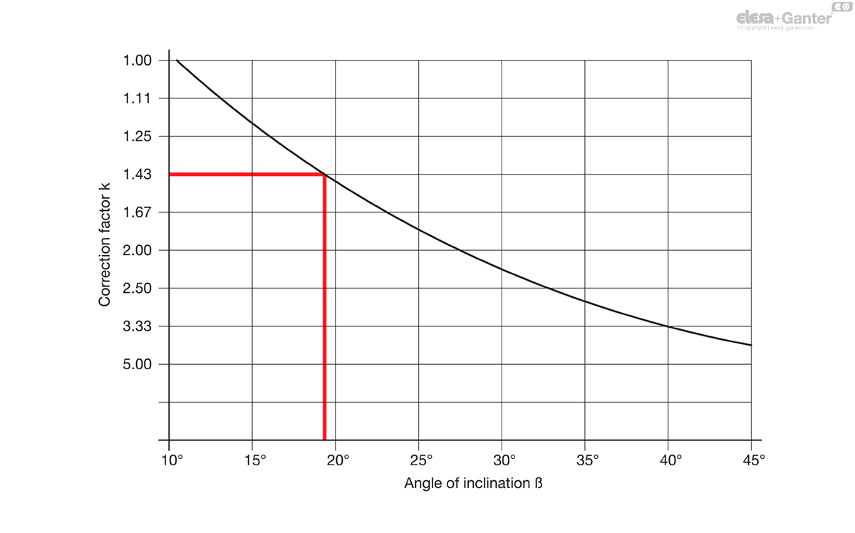
Example 2
Torque to be transferred M = 23 Nm
R.p.m. n = 2300 min-1
Angle of inclination ß = 18°
Correction coefficient k = 1.43
Indicative torque = 1.43 x 23 Nm = 33 Nm
Intersection point P1 results from 33 Nm and 2300 min-1 (which is equivalent to an indicative output N = 7.9 kW).
The next size up universal joint corresponding to P1 is the model with a diameter d1 = 32.
DIN-808-ST
| Color | d1 | d2 H7 Bore |
s H10 Square | l1 | l2 | l3 | l4 | t+1 Assembly length of the shaft | |||
|---|---|---|---|---|---|---|---|---|---|---|---|
| Code | Actions | ||||||||||
| DIN 808-22-B10-48-EW | B-EW | 22 | 10 | - | 48 | - | 24 | - | 12 | 95 |
|
| DIN 808-22-B10-74-DW | B-DW | 22 | 10 | - | - | 74 | 24 | 26 | 12 | 140 |
|
| DIN 808-22-B12-62-EW | B-EW | 22 | 12 | - | 62 | - | 31 | - | 18 | 118 |
|
| DIN 808-22-B12-88-DW | B-DW | 22 | 12 | - | - | 88 | 31 | 26 | 18 | 170 |
|
| DIN 808-22-K10-48-EW | K-EW | 22 | 10 | - | 48 | - | 24 | - | 12 | 95 |
|
| DIN 808-22-K10-74-DW | K-DW | 22 | 10 | - | - | 74 | 24 | 26 | 12 | 141 |
|
| DIN 808-22-K12-62-EW | K-EW | 22 | 12 | - | 62 | - | 31 | - | 18 | 116 |
|
| DIN 808-22-K12-88-DW | K-DW | 22 | 12 | - | - | 88 | 31 | 26 | 18 | 163 |
|
| DIN 808-22-V10-48-EW | V-EW | 22 | - | V 10* | 48 | - | 24 | - | 12 | 92 |
|
| DIN 808-22-V10-62-EW | V-EW | 22 | - | V 10* | 62 | - | 31 | - | 18 | 123 |
|
| DIN 808-22-V10-74-DW | V-DW | 22 | - | V 10* | - | 74 | 24 | 26 | 12 | 142 |
|
| DIN 808-22-V10-88-DW | V-DW | 22 | - | V 10* | - | 88 | 31 | 26 | 18 | 175 |
|
| DIN 808-25-B12-56-EW | B-EW | 25 | 12 | - | 56 | - | 28 | - | 13 | 145 |
|
| DIN 808-25-B12-86-DW | B-DW | 25 | 12 | - | - | 86 | 28 | 30 | 13 | 216 |
|
| DIN 808-25-B16-74-EW | B-EW | 25 | 16 | - | 74 | - | 37 | - | 21 | 165 |
|
| DIN 808-25-B16-104-DW | B-DW | 25 | 16 | - | - | 104 | 37 | 30 | 21 | 235 |
|
| DIN 808-25-K12-56-EW | K-EW | 25 | 12 | - | 56 | - | 28 | - | 13 | 142 |
|
| DIN 808-25-K12-86-DW | K-DW | 25 | 12 | - | - | 86 | 28 | 30 | 13 | 212 |
|
| DIN 808-25-K16-74-EW | K-EW | 25 | 16 | - | 74 | - | 37 | - | 21 | 162 |
|
| DIN 808-25-K16-104-DW | K-DW | 25 | 16 | - | - | 104 | 37 | 30 | 21 | 231 |
|
| DIN 808-25-V12-56-EW | V-EW | 25 | - | V 12* | 56 | - | 28 | - | 13 | 144 |
|
| DIN 808-25-V12-74-EW | V-EW | 25 | - | V 12* | 74 | - | 37 | - | 21 | 192 |
|
| DIN 808-25-V12-86-DW | V-DW | 25 | - | V 12* | - | 86 | 28 | 30 | 13 | 208 |
|
| DIN 808-25-V12-104-DW | V-DW | 25 | - | V 12* | - | 104 | 37 | 30 | 21 | 260 |
|
| DIN 808-28-B14-60-EW | B-EW | 28 | 14 | - | 60 | - | 30 | - | 13 | 183 |
|
| DIN 808-28-B14-96-DW | B-DW | 28 | 14 | - | - | 96 | 30 | 36 | 13 | 287 |
|
| DIN 808-28-K14-60-EW | K-EW | 28 | 14 | - | 60 | - | 30 | - | 13 | 180 |
|
| DIN 808-28-K14-96-DW | K-DW | 28 | 14 | - | - | 96 | 30 | 36 | 13 | 280 |
|
| DIN 808-28-V14-60-EW | V-EW | 28 | - | V 14* | 60 | - | 30 | - | 13 | 174 |
|
| DIN 808-28-V14-96-DW | V-DW | 28 | - | V 14* | - | 96 | 30 | 36 | 13 | 288 |
|
| DIN 808-32-B16-68-EW | B-EW | 32 | 16 | - | 68 | - | 34 | - | 16 | 284 |
|
| DIN 808-32-B16-105-DW | B-DW | 32 | 16 | - | - | 105 | 34 | 37 | 16 | 424 |
|
| DIN 808-32-B20-86-EW | B-EW | 32 | 20 | - | 86 | - | 43 | - | 24 | 320 |
|
| DIN 808-32-B20-124-DW | B-DW | 32 | 20 | - | - | 124 | 43 | 38 | 24 | 461 |
|
| DIN 808-32-K16-68-EW | K-EW | 32 | 16 | - | 68 | - | 34 | - | 16 | 279 |
|
| DIN 808-32-K16-105-DW | K-DW | 32 | 16 | - | - | 105 | 34 | 37 | 16 | 417 |
|
| DIN 808-32-K20-86-EW | K-EW | 32 | 20 | - | 86 | - | 43 | - | 24 | 313 |
|
| DIN 808-32-K20-124-DW | K-DW | 32 | 20 | - | - | 124 | 43 | 38 | 24 | 453 |
|
| DIN 808-32-V16-68-EW | V-EW | 32 | - | V 16* | 68 | - | 34 | - | 16 | 270 |
|
| DIN 808-32-V16-86-EW | V-EW | 32 | - | V 16* | 86 | - | 43 | - | 24 | 358 |
|
| DIN 808-32-V16-105-DW | V-DW | 32 | - | V 16* | - | 105 | 34 | 37 | 16 | 414 |
|
| DIN 808-32-V16-124-DW | V-DW | 32 | - | V 16* | - | 124 | 43 | 38 | 24 | 488 |
|
| DIN 808-36-B18-74-EW | B-EW | 36 | 18 | - | 74 | - | 37 | - | 17 | 378 |
|
| DIN 808-36-B18-114-DW | B-DW | 36 | 18 | - | - | 114 | 37 | 40 | 17 | 554 |
|
| DIN 808-36-K18-74-EW | K-EW | 36 | 18 | - | 74 | - | 37 | - | 17 | 373 |
|
| DIN 808-36-K18-114-DW | K-DW | 36 | 18 | - | - | 114 | 37 | 40 | 17 | 558 |
|
| DIN 808-36-V18-74-EW | V-EW | 36 | - | V 18* | 74 | - | 37 | - | 17 | 380 |
|
| DIN 808-36-V18-114-DW | V-DW | 36 | - | V 18* | - | 114 | 37 | 40 | 17 | 536 |
|
| DIN 808-42-B20-82-EW | B-EW | 42 | 20 | - | 82 | - | 41 | - | 18 | 450 |
|
| DIN 808-42-B20-128-DW | B-DW | 42 | 20 | - | - | 128 | 41 | 46 | 18 | 898 |
|
| DIN 808-42-B25-108-EW | B-EW | 42 | 25 | - | 108 | - | 54 | - | 31 | 718 |
|
| DIN 808-42-B25-156-DW | B-DW | 42 | 25 | - | - | 156 | 54 | 48 | 31 | 1025 |
|
| DIN 808-42-K20-82-EW | K-EW | 42 | 20 | - | 82 | - | 41 | - | 18 | 595 |
|
| DIN 808-42-K20-128-DW | K-DW | 42 | 20 | - | - | 128 | 41 | 46 | 18 | 889 |
|
| DIN 808-42-K25-108-EW | K-EW | 42 | 25 | - | 108 | - | 54 | - | 31 | 703 |
|
| DIN 808-42-K25-156-DW | K-DW | 42 | 25 | - | - | 156 | 54 | 48 | 31 | 1006 |
|
| DIN 808-42-V20-82-EW | V-EW | 42 | - | V 20* | 82 | - | 41 | - | 18 | 572 |
|
| DIN 808-42-V20-108-EW | V-EW | 42 | - | V 20* | 108 | - | 54 | - | 31 | 774 |
|
| DIN 808-42-V20-128-DW | V-DW | 42 | - | V 20* | - | 128 | 41 | 46 | 18 | 880 |
|
| DIN 808-42-V20-156-DW | V-DW | 42 | - | V 20* | - | 156 | 54 | 48 | 31 | 1060 |
|
| DIN 808-45-B22-95-EW | B-EW | 45 | 22 | - | 95 | - | 47.5 | - | 22 | 771 |
|
| DIN 808-45-B22-145-DW | B-DW | 45 | 22 | - | - | 145 | 47.5 | 50 | 22 | 1125 |
|
| DIN 808-45-K22-95-EW | K-EW | 45 | 22 | - | 95 | - | 47.5 | - | 22 | 771 |
|
| DIN 808-45-K22-145-DW | K-DW | 45 | 22 | - | - | 145 | 47.5 | 50 | 22 | 1117 |
|
| DIN 808-45-V22-95-EW | V-EW | 45 | - | V 22* | 95 | - | 47.5 | - | 22 | 740 |
|
| DIN 808-45-V22-145-DW | V-DW | 45 | - | V 22* | - | 145 | 47.5 | 50 | 22 | 1108 |
|
| DIN 808-50-B25-108-EW | B-EW | 50 | 25 | - | 108 | - | 54 | - | 26 | 1095 |
|
| DIN 808-50-B25-163-DW | B-DW | 50 | 25 | - | - | 163 | 54 | 55 | 26 | 1594 |
|
| DIN 808-50-B30-132-EW | B-EW | 50 | 30 | - | 132 | - | 66 | - | 38 | 1234 |
|
| DIN 808-50-B30-188-DW | B-DW | 50 | 30 | - | - | 188 | 66 | 56 | 38 | 1751 |
|
| DIN 808-50-K25-108-EW | K-EW | 50 | 25 | - | 108 | - | 54 | - | 26 | 1085 |
|
| DIN 808-50-K25-163-DW | K-DW | 50 | 25 | - | - | 163 | 54 | 55 | 26 | 1590 |
|
| DIN 808-50-K30-132-EW | K-EW | 50 | 30 | - | 132 | - | 66 | - | 38 | 1229 |
|
| DIN 808-50-K30-188-DW | K-DW | 50 | 30 | - | - | 188 | 66 | 56 | 38 | 1714 |
|
| DIN 808-50-V25-108-EW | V-EW | 50 | - | V 25* | 108 | - | 54 | - | 26 | 1038 |
|
| DIN 808-50-V25-132-EW | V-EW | 50 | - | V 25* | 132 | - | 66 | - | 38 | 1250 |
|
| DIN 808-50-V25-163-DW | V-DW | 50 | - | V 25* | - | 163 | 54 | 55 | 26 | 1518 |
|
| DIN 808-50-V25-188-DW | V-DW | 50 | - | V 25* | - | 188 | 66 | 56 | 38 | 1780 |
|
| DIN 808-58-B30-122-EW | B-EW | 58 | 30 | - | 122 | - | 61 | - | 29 | 1653 |
|
| DIN 808-58-B30-190-DW | B-DW | 58 | 30 | - | - | 190 | 61 | 68 | 29 | 2496 |
|
| DIN 808-58-B32-130-EW | B-EW | 58 | 32 | - | 130 | - | 65 | - | 33 | 1723 |
|
| DIN 808-58-B32-198-DW | B-DW | 58 | 32 | - | - | 198 | 65 | 68 | 33 | 2552 |
|
| DIN 808-58-K30-122-EW | K-EW | 58 | 30 | - | 122 | - | 61 | - | 29 | 1631 |
|
| DIN 808-58-K30-190-DW | K-DW | 58 | 30 | - | - | 190 | 61 | 68 | 29 | 2513 |
|
| DIN 808-58-K32-130-EW | K-EW | 58 | 32 | - | 130 | - | 65 | - | 33 | 1718 |
|
| DIN 808-58-K32-198-DW | K-DW | 58 | 32 | - | - | 198 | 65 | 68 | 33 | 2541 |
|
| DIN 808-58-V30-122-EW | V-EW | 58 | - | V 30* | 122 | - | 61 | - | 29 | 1550 |
|
| DIN 808-58-V30-130-EW | V-EW | 58 | - | V 30* | 130 | - | 65 | - | 33 | 1250 |
|
| DIN 808-58-V30-190-DW | V-DW | 58 | - | V 30* | - | 190 | 61 | 68 | 29 | 2350 |
|
| DIN 808-58-V30-198-DW | V-DW | 58 | - | V 30* | - | 198 | 65 | 68 | 33 | 2541 |
|
| DIN 808-70-B35-140-EW | B-EW | 70 | 35 | - | 140 | - | 70 | - | 35 | 2750 |
|
| DIN 808-70-B35-212-DW | B-DW | 70 | 35 | - | - | 212 | 70 | 72 | 35 | 2040 |
|
| DIN 808-70-K35-140-EW | K-EW | 70 | 35 | - | 140 | - | 70 | - | 35 | 2760 |
|
| DIN 808-70-K35-212-DW | K-DW | 70 | 35 | - | - | 212 | 70 | 72 | 35 | 2043 |
|
| DIN 808-70-V35-140-EW | V-EW | 70* | - | V 35 | 140 | - | 70 | - | 35 | 2630 |
|
| DIN 808-70-V35-212-DW | V-DW | 70* | - | V 35 | - | 212 | 70 | 72 | 35 | 2042 |
|

Enquiry Now
To allow us to respond to your enquiry promptly, please provide all required information.
Related Products
-
 GN 808.3Universal joint shafts with needle bearingwith longitudinal compensationView Product
 -
 GN 808.2Universal Joint Shafts with Friction Bearingwith Longitudinal CompensationView Product
 -
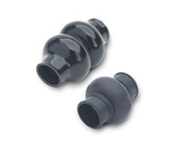 GN 808.1Gaitersfor universal joints DIN 808View Product
 -
 GN 9080Universal JointsSteel, for Ordinary ApplicationsView Product

