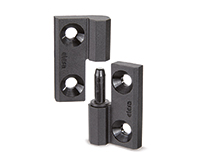
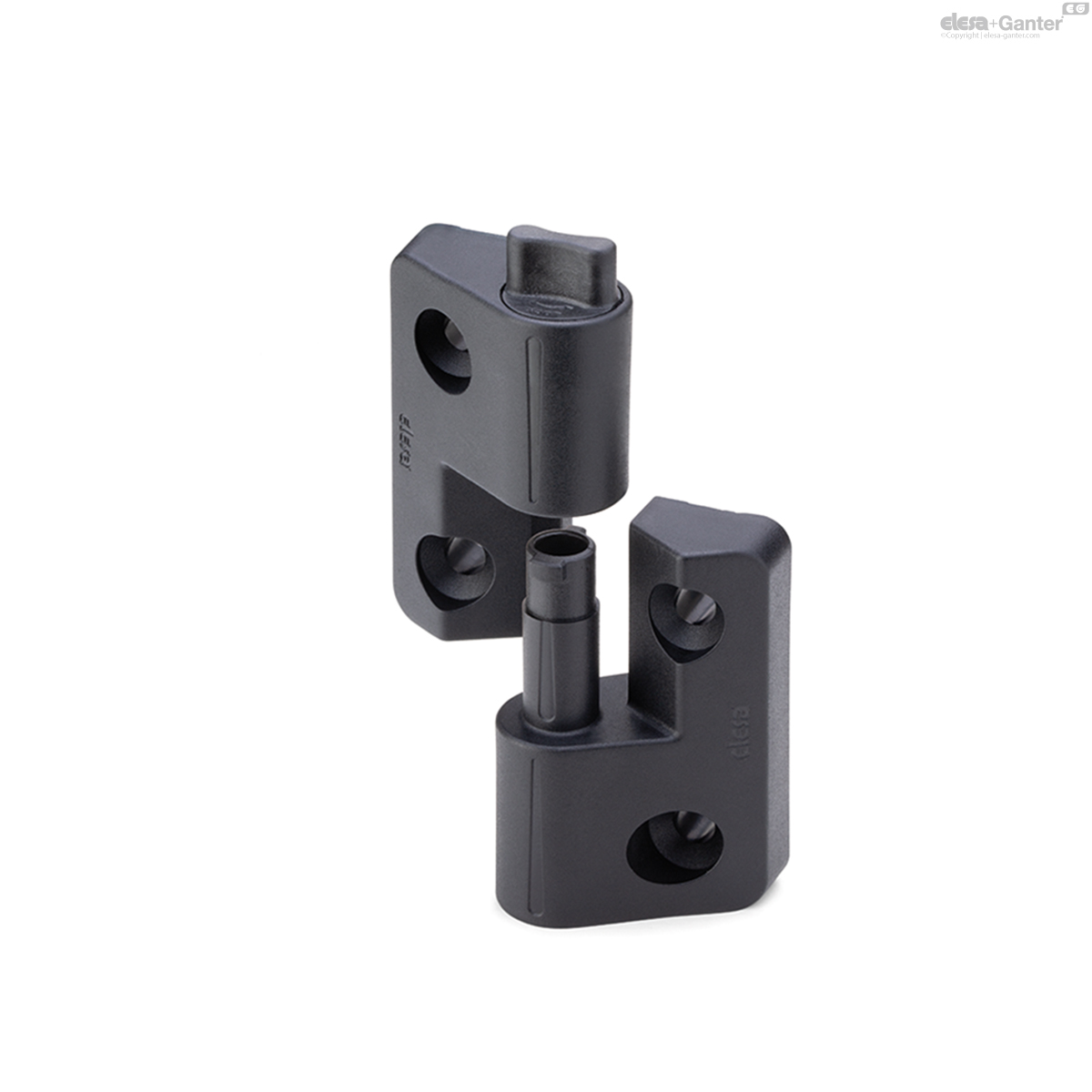
CFMY-NL
Lift-off hinges
with locking/unlocking system, technopolymer
CFMY-NL-M-D
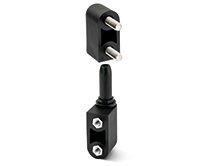
Lift-off hinges
With built-in key, pin in the right body
CFMY-NL-M-S
Lift-off hinges
With built-in key, pin in the left body
CFMY-NL-T-D
Lift-off hinges
With hexagonal key, pin in the right body
CFMY-NL-T-S
Lift-off hinges
With hexagonal key, pin in the left body

Description
Main specifications
Material
- Hinge body: glass-fibre reinforced polyamide based (PA) technopolymer, black colour, matte finish.
- Locking/unlocking system: acetal resin based (POM) technopolymer.
Standard executions
Pass-through holes for countersunk head screws.
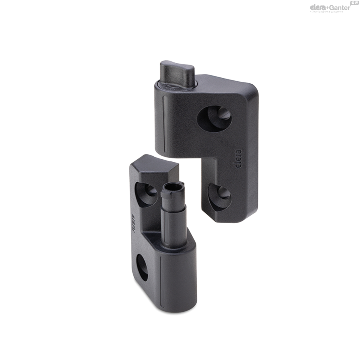
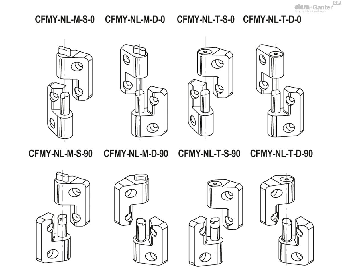
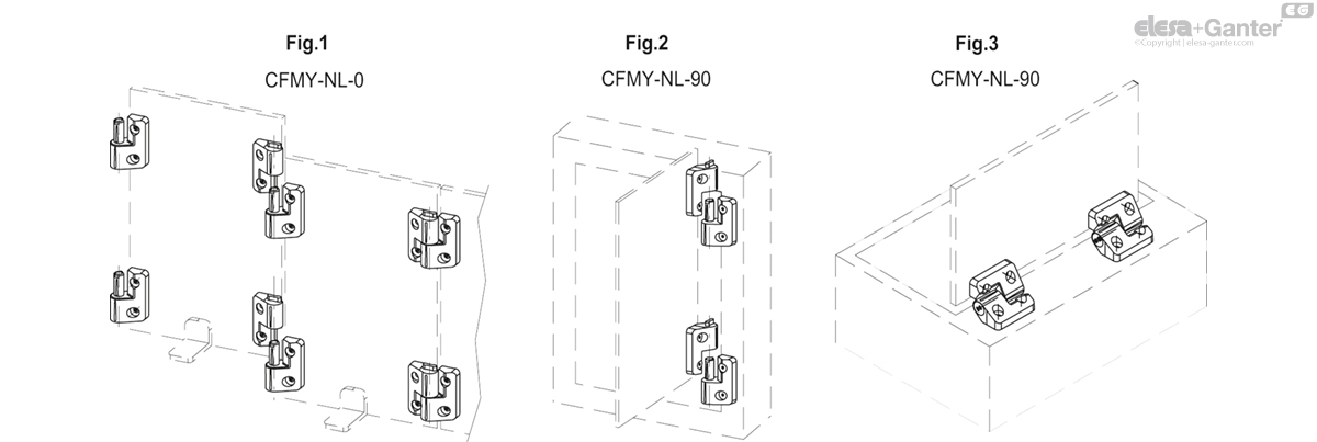
Coupling angle 0 degrees: suitable for quickly creating a perimeter protection or a divider that can be easily modified or moved (Fig.1).
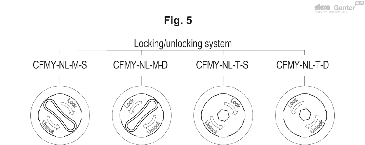
Locking/unlocking system with built-in key:
- CFMY-NL-M-S-0: rotation pin fitted on the left hinge body.
- CFMY-NL-M-D-0: rotation pin fitted on the right hinge body.
Locking/unlocking system with hexagonal key:
- CFMY-NL-T-S-0: rotation pin fitted on the left hinge body.
- CFMY-NL-T-D-0: rotation pin fitted on the right hinge body.
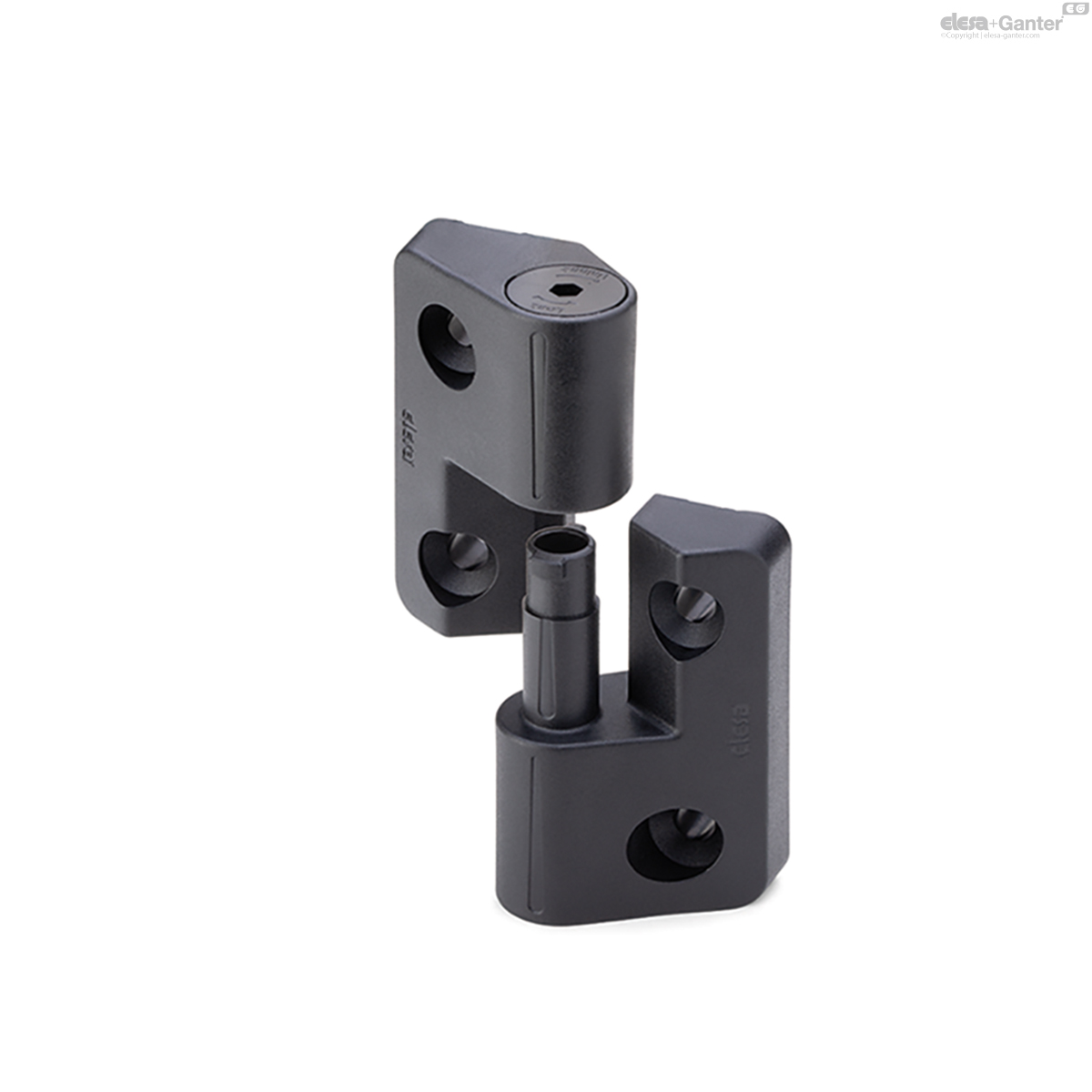
90 degree coupling angle: suitable for assembling/dismantling a door positioned on a structure (Fig.2).
Locking/unlocking system with built-in key:
- CFMY-NL-M-S-90: rotation pin fitted on the left hinge body.
- CFMY-NL-M-D-90: rotation pin fitted on the right hinge body.
Locking/unlocking system with hexagonal key:
- CFMY-NL-T-S-90: rotation pin fitted on the left hinge body.
- CFMY-NL-T-D-90: rotation pin fitted on the right hinge body.

General information
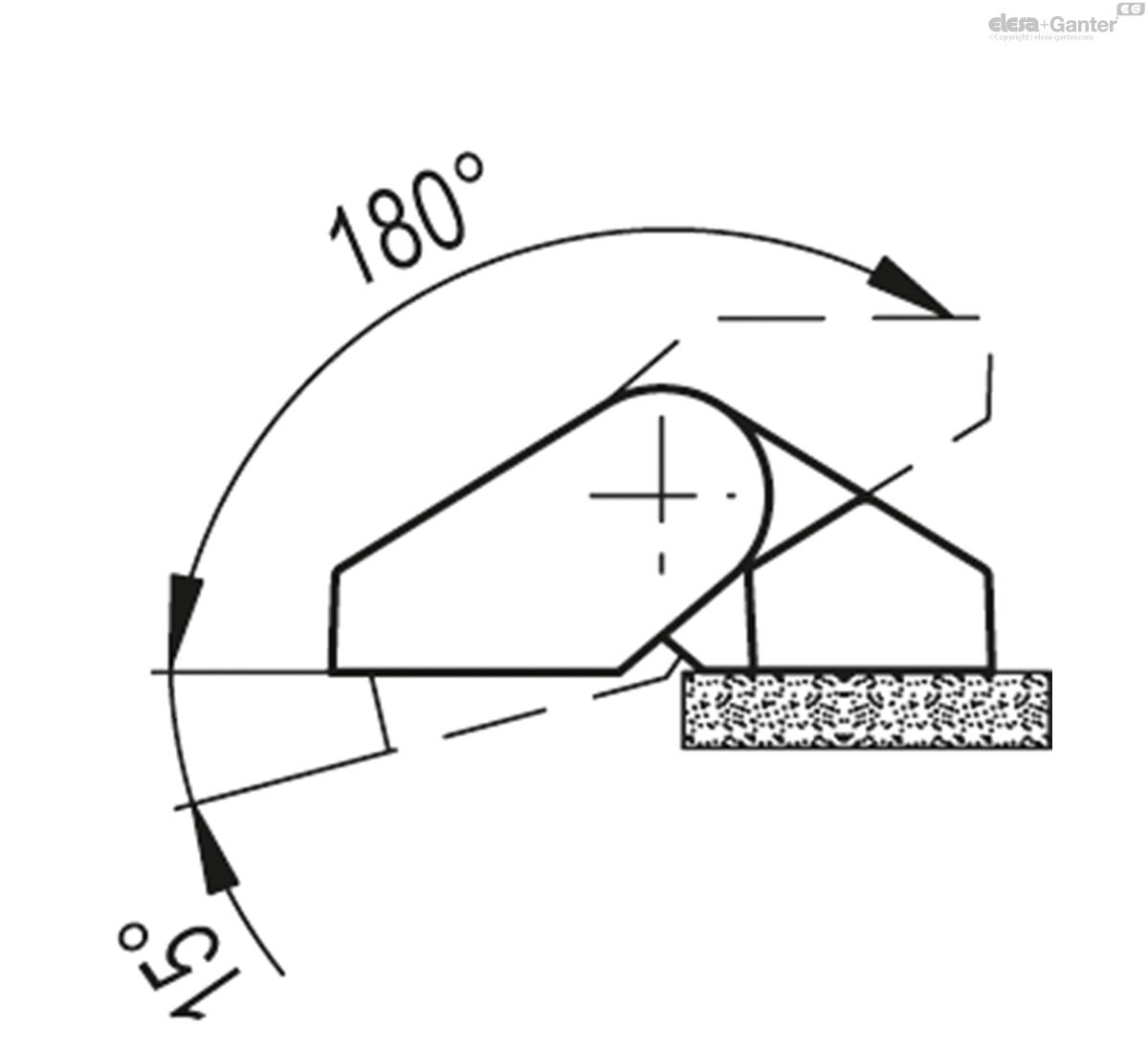
Rotation angle (approximate value)
Max 195° (-15° and +180° being 0° the condition where the interconnected surfaces are on the same plane).
Do not exceed the rotation angle limit so as not to prejudice the hinge mechanical performance.
To choose the convenient type and the right number of hinges for your application, see the Guidelines.
Features and applications
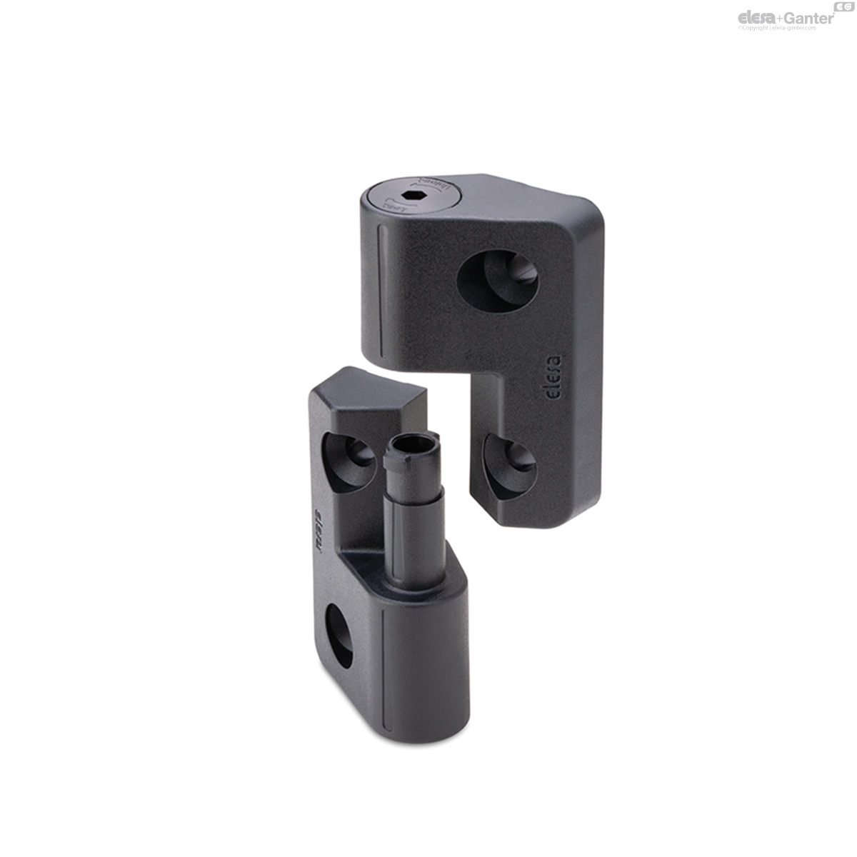
The CFMY-NL hinge is a hinge for removable doors equipped with a mechanical lock, which can be activated via a hexagonal key or a key, which allows the two sides of the hinge to be locked axially together, thus preventing the door from lifting and sliding out involuntarily.
This mechanical lock therefore allows the application of the product on doors with a horizontal axis (hatch type), preventing pull-out even in the event of accidental opening (Fig.3).

| Resistance tests | Axial Stress* | Radial Stress | 90° Angled Stress |
| Description | Max limit static load Sa [N] | Max limit static load Sr [N] | Max limit static load S90 [N] |
| CFMY.60-NL | 500 | 700 | 700 |
The max static load is the value above which the material may break thus prejudicing the hinge functionality. Obviously, a suitable factor, according to the importance and the safety level of the specific application must be applied to this value.
* in the opposite direction to the coupling of the two sides
Instructions of use
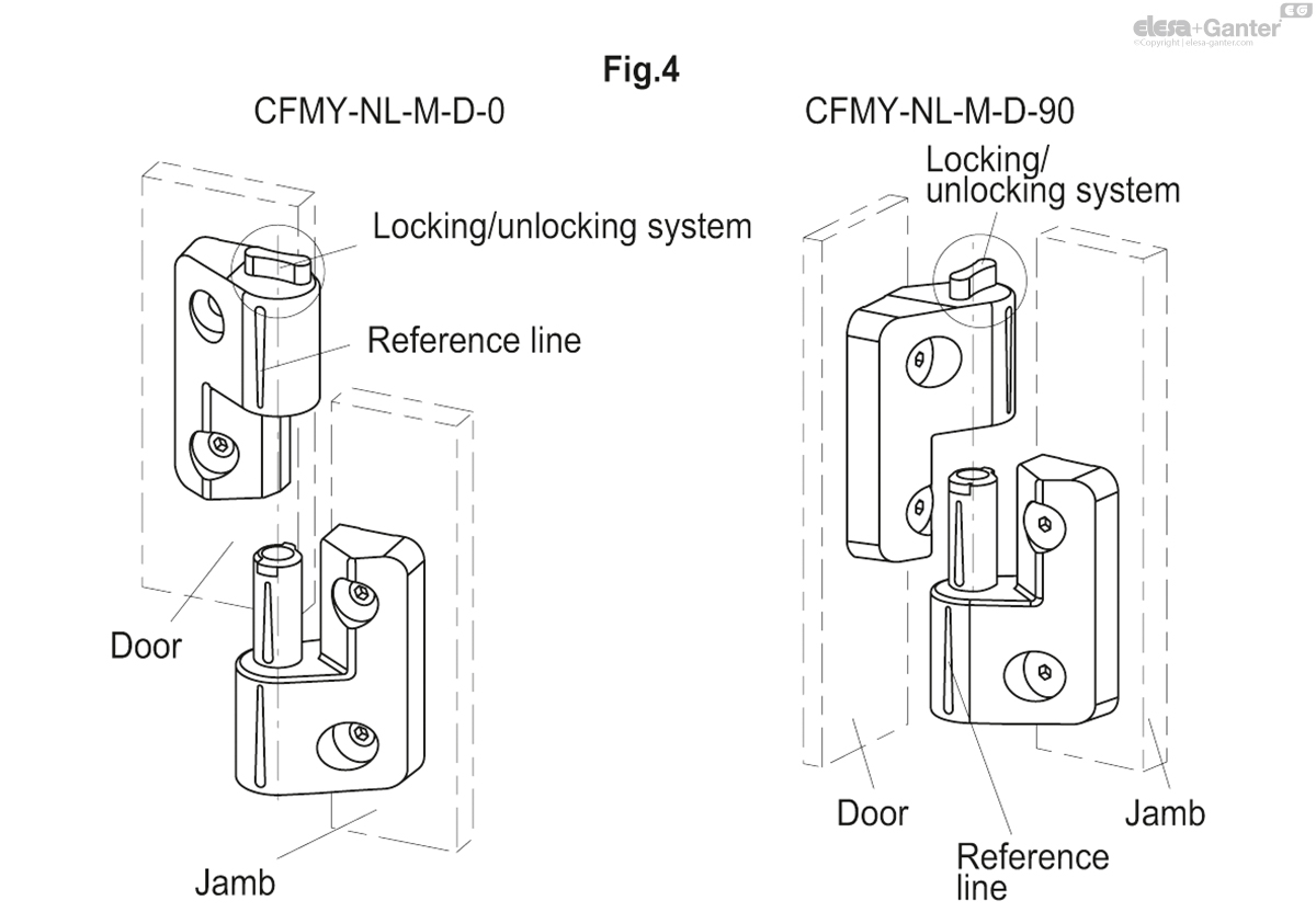
Assembly instructions (Fig.4)
0° coupling angle:
- install the hinge side containing the rotation pin on the jamb
- fit the door side hinge seat onto the jamb side hinge pin, checking that the two planes are coplanar and that the reference lines on the two sides of the hinge are aligned
- once installation is complete, rotate the locking system all the way (lock position)
90° coupling angle:
- install the hinge side containing the rotation pin on the jamb
- fit the seat of the hinge on the door side onto the hinge pin on the jamb side, checking that the two surfaces are rotated by 90° to each other
- once installation is complete, rotate the locking system all the way (lock position)
Disassembly instructions
- rotate the locking system to the unlock position
- bring the hinge to the coupling position (0 or 90°)
- lift the door free with both hands


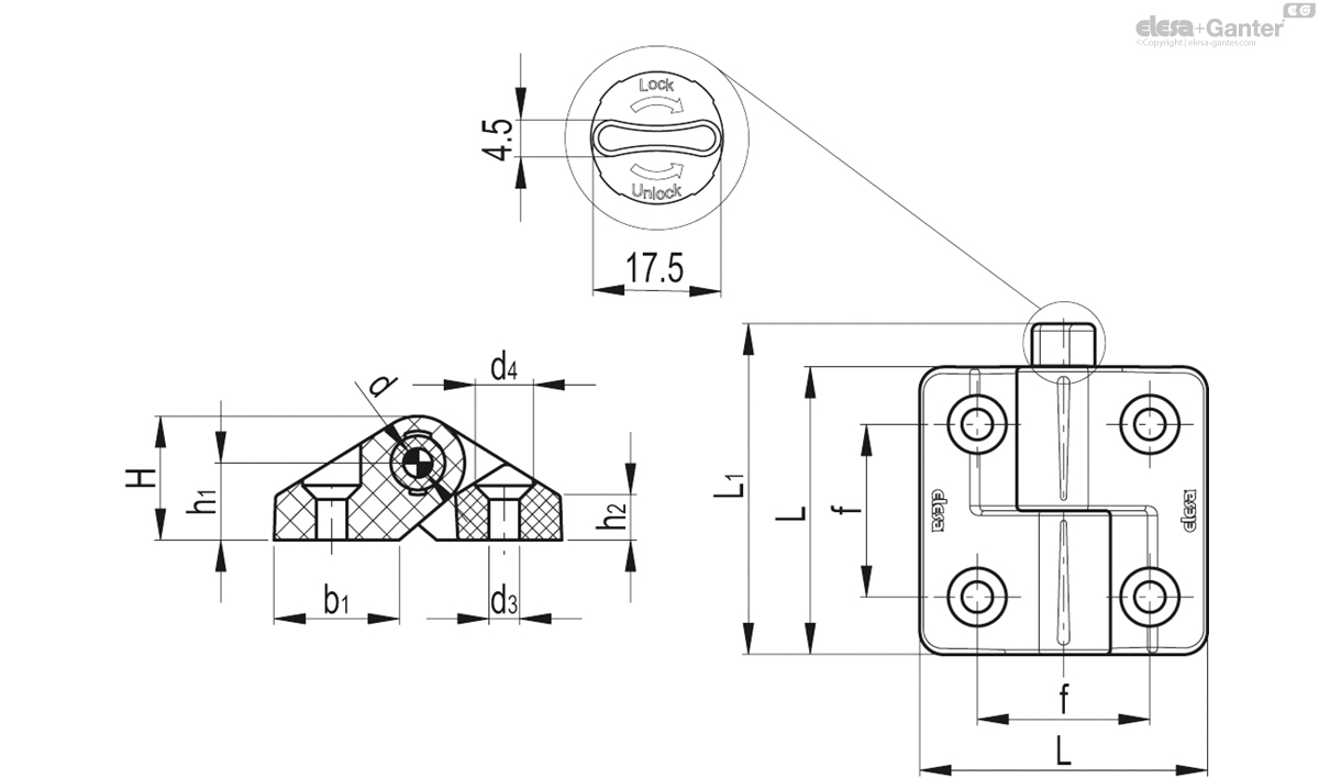
CFMY-NL-M-S
| L | f±0.25 | H | h1 | h2 | b1 | L1 | d | d3 | d4 | C# [Nm] |
Resistance to opening* [N] |
||||
|---|---|---|---|---|---|---|---|---|---|---|---|---|---|---|---|
| Code | Description | Actions | |||||||||||||
| 425992 | CFMY.60-NL-M-S-0 | 60 | 36 | 26 | 16 | 9 | 26 | 69 | 11 | 6.5 | 12 | 5 | 300 | 50 |
|
| 425994 | CFMY.60-NL-M-S-90 | 60 | 36 | 26 | 16 | 9 | 26 | 69 | 11 | 6.5 | 12 | 5 | 300 | 50 |
|

Enquiry Now
To allow us to respond to your enquiry promptly, please provide all required information.